
EBK THE ANALYSIS AND DESIGN OF LINEAR C
8th Edition
ISBN: 9781119140320
Author: Toussaint
Publisher: VST
expand_more
expand_more
format_list_bulleted
Videos
Textbook Question
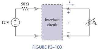
Chapter 3, Problem 3.100IP
Interface Circuit Design
Using no more than three
Expert Solution & Answer
Want to see the full answer?
Check out a sample textbook solution
Students have asked these similar questions
For the circuit below, determine the resistor current.The source is 6V, the Zener potential is 5V and the resistor is 5k.
For very large resistances it is easy to construct R-C circuits that have time constants of several seconds or minutes. How might this fact be used to measure very large resistances, those that are too large to measure by more conventional means?
4.For the circuit below, consider that the switch is in the "a" position only, for a long time Consider R1= R2 = R3 = 18ohm,R4= R5=9ohm, R6 = 3ohm, L=5mH and C=10uF get the constant of time for the first order circuit, with the switch in the "a" position.
Chapter 3 Solutions
EBK THE ANALYSIS AND DESIGN OF LINEAR C
Ch. 3 - Formulate node-voltage equations for the circuit...Ch. 3 - (a) Formulate node-voltage equations for the...Ch. 3 - (a) Formulate node-voltage equations for the...Ch. 3 - Formulate node-voltage equations for the circuit...Ch. 3 - (a) Formulate node-voltage equations for the...Ch. 3 - Choose a ground wisely and formulate node-voltage...Ch. 3 - The following are a set of node-voltage equations;...Ch. 3 - Choose a ground wisely and formulate node-voltage...Ch. 3 - Formulate node-voltage equations for the circuit...Ch. 3 - Formulate node-voltage equations for the circuit...
Ch. 3 - (a) Formulate mesh-current equations for the...Ch. 3 - (a) Formulate mesh-current equations for the...Ch. 3 - (a) Formulate mesh-current equations for the...Ch. 3 - Prob. 3.16PCh. 3 - Formulate mesh-current equations for the circuit...Ch. 3 - For the circuit of figure P3-19 solve for iA,iB,...Ch. 3 - Formulate mesh-current equations for the circuit...Ch. 3 - The circuit in Figure P3-21 seems to require two...Ch. 3 - Formulate mesh-current equations for the circuit...Ch. 3 - Use simple engineering intuition to find the input...Ch. 3 - In Figure P3-24 all of the resistors are 1k and...Ch. 3 - Use Figure P3-24 and MATLAB to solve the following...Ch. 3 - Formulate mesh-current equations for the circuit...Ch. 3 - Find vO for the block diagram shown in figure...Ch. 3 - Design a voltage-divider circuit that will realize...Ch. 3 - Design a current-divider circuit that will realize...Ch. 3 - Using a single resistor, design a circuit that...Ch. 3 - Find the proportionality constant K=vO/vS for the...Ch. 3 - Find the proportionality constant K=iO/vS for the...Ch. 3 - Find the proportionality constant K=vO/iS for the...Ch. 3 - Find the proportionality constant K=iO/iS for the...Ch. 3 - Find the proportionality constant K=vO/vS for the...Ch. 3 - Use the unit output method to find K and vO in...Ch. 3 - Use the unit output method to find K and vO in...Ch. 3 - Use the unit output method to find K in Figure...Ch. 3 - Use the superposition principle to find vO in...Ch. 3 - Use the superposition principle to find vO in...Ch. 3 - Use the superposition principle to find vO in...Ch. 3 - (a) Use the superposition principle to find vO in...Ch. 3 - A linear circuit containing two sources drives a...Ch. 3 - A block diagram of a linear circuit is shown in...Ch. 3 - A certain linear circuit has four input voltages...Ch. 3 - When the current source is turned off in the...Ch. 3 - For the circuit in Figure P3—51, find the Thévenin...Ch. 3 - For the circuit in Figure P3—52, find the Thévenin...Ch. 3 - For the circuit of Figure P3—53, find the Thévenin...Ch. 3 - Find the Thévenin or Norton equivalent circuit...Ch. 3 - Find the Thévenin or Norton equivalent circuit...Ch. 3 - Find the Thévenin equivalent circuit seen by RL in...Ch. 3 - Find the Norton equivalent seen by RL in Figure...Ch. 3 - You need to determine the Thévenin equivalent...Ch. 3 - Find the Thévenin equivalent seen by RL in figure...Ch. 3 - The purpose of this problem is to use Thévenin...Ch. 3 - The circuit in Figure P3-62 was solved earlier...Ch. 3 - Assume that Figure P3-63 represents a model of the...Ch. 3 - The iv characteristic of the active circuit...Ch. 3 - You have successfully completed the first course...Ch. 3 - The Thévenin equivalent parameters of a practical...Ch. 3 - Use a sequence of source transformations to find...Ch. 3 - The circuit in Figure P3-68 provides power to a...Ch. 3 - A nonlinear resistor is connected across a...Ch. 3 - Prob. 3.71PCh. 3 - Find the Norton equivalent seen by RL in Figure...Ch. 3 - Find the Thévenin equivalent seen by RL in Figure...Ch. 3 - Find the Thévenin equivalent seen by RL in Figure...Ch. 3 - For the circuit of Figure P3-75, find the value of...Ch. 3 - For the circuit of Figure P3-76, find the value of...Ch. 3 - The resistance R in Figure P3-77 is adjusted until...Ch. 3 - When a 5-k resistor is connected across a...Ch. 3 - Find the value of R in the circuit of Figure P3-79...Ch. 3 - For the circuit of Figure P3-80, find the value of...Ch. 3 - A 1-k load needs 10 mA to operate correctly....Ch. 3 - A practical source delivers 25 mA to a load. The...Ch. 3 - A 10-V source is shown in Figure P3-83 that is...Ch. 3 - (a)Select RL and design an interface circuit for...Ch. 3 - The source in Figure P3-85 has a 100-mA output...Ch. 3 - Figure P3-86 shows an interface circuit connecting...Ch. 3 - Prob. 3.87PCh. 3 - In this problem, you will design two interface...Ch. 3 - Two teams are competing to design the interface...Ch. 3 - The bridge-T attenuation pad shown in FigureP3-90...Ch. 3 - Design two interface circuits in Figure P3-91 so...Ch. 3 - Design the interface circuit in Figure P3-91 so...Ch. 3 - Design the interface circuit in Figure P3-93 so...Ch. 3 - It is claimed that both interface circuits in...Ch. 3 - Audio Speaker Resistance-Matching Network A...Ch. 3 - Interface Circuit Design Using no more than three...Ch. 3 - Battery Design A satellite requires a battery with...Ch. 3 - Design Interface Competition The output of a...Ch. 3 - Prob. 3.106IP
Knowledge Booster


Learn more about
Need a deep-dive on the concept behind this application? Look no further. Learn more about this topic, electrical-engineering and related others by exploring similar questions and additional content below.Similar questions
- Solve the given two circuits by your choice of approach and find. a) Total Current and Total Resistance. b) Voltage and current through R5. R2 302 202 R1 200 R4 602R3 + B1= 40V R6 30n 40n3 R5arrow_forwardsolve this onearrow_forward8-13 E (a) Formulate mesh-current equations for the cir- cuit in Figure P3-13. (b) Formulate node-voltage equations for the circuit in Figure P3-13. (c) Which set of equations would be easier to solve? Why? (d) Using MATLAB, find , and i, in terms of the mesh- current variables. SSarrow_forward
- %3D For the following circuit, calculate the current through R5 and the voltage drop across R5. Use the following parameters for the circuit: Vs = 8 V, R1 = 48, R2 = 8, R2 = 4, R4 = 5, R5 = 20. Rz R3 R5 R4arrow_forwardQ5 A linear circuit is shown below in Figure 5-1. www R3 9mvA R₁ ww + VA- + R₂VB Figure 5-1 Vs The elements in this circuit have the following values: R₁ = 1000, R₂ = 2000, R3 = 350, V = 5V, and 9m = 0.004A/V. Determine the potentials drops and ug across resistors R₁ and R₂ respectively. (a) What is the value of voltage UA in Volts? 1arrow_forwardUse the Principle of Superposition to determine the current i through R3 in the Figure. Let R1 = 100, R2 = 40, R3 = 20, R4 = 20, R5= 20, Vs 10 V, Is = 2A. ww VS R3 ww wwwarrow_forward
- in this question, the answer should be C because wwe need to take the total voltage over the total resistance. However, for C to be the correct answer, that means we need to assume that the resistors are in parallel to calculate the total resistance. However, it appears to me that R1 is not parallel to R2 since they do not share the same two nodes? Can you explain why that is?arrow_forwardThis Homework is too much... i already solved 3 question but still alot to go.. Please Help me Solve this.arrow_forwardThe image contains the problems that need to be solved. This is a voltage divider circuit, and it is understood that V0 is maximized when one of the resistors is at its maximum value while the other is at its minimum (and vice versa for the minimum V0). The answers are provided, but the process is needed.arrow_forward
- Interface Circuit Design 3-24 KE Audio Speaker Resistance-Matching Network A company is producing an interface network that they claim would result in an Rin of 600 2 ±2% and RoUT of 16, 8, or 40 ±2%-depending on whether the connected speakers are 16, 8, or 4 S2-selectable via a built-in switch. The design is shown in Figure P3-24. Prove or disprove their claim. 600 2 592 2 8 Ω 16 Ω vs 4Ω 4Ω 4Ω |16, 8, or 4 2 Audio matching network FIGURE P3–24arrow_forward9. The circuit shown in the figure is an example of a voltage divider. The potential difference ɛ is divided by R1 and R2, and only a fraction of the voltage appears across the load resistor, RL. Calculate the value of R2 so that the voltage across Rį is 4 V when ɛ = 20 V, R1 = 80 n and R, = 600 N. R2arrow_forwardFor R1=70, R2=95, R3-60 and R4-30 Calculate the equivalent resistance at terminals a-b for the shown circuit. bo R4 www R3 (a) www R2 R1 The equivalent resistance (in ohm) =arrow_forward
arrow_back_ios
SEE MORE QUESTIONS
arrow_forward_ios
Recommended textbooks for you
 Introductory Circuit Analysis (13th Edition)Electrical EngineeringISBN:9780133923605Author:Robert L. BoylestadPublisher:PEARSON
 Delmar's Standard Textbook Of ElectricityElectrical EngineeringISBN:9781337900348Author:Stephen L. HermanPublisher:Cengage Learning
 Programmable Logic ControllersElectrical EngineeringISBN:9780073373843Author:Frank D. PetruzellaPublisher:McGraw-Hill Education
 Fundamentals of Electric CircuitsElectrical EngineeringISBN:9780078028229Author:Charles K Alexander, Matthew SadikuPublisher:McGraw-Hill Education
 Electric Circuits. (11th Edition)Electrical EngineeringISBN:9780134746968Author:James W. Nilsson, Susan RiedelPublisher:PEARSON
 Engineering ElectromagneticsElectrical EngineeringISBN:9780078028151Author:Hayt, William H. (william Hart), Jr, BUCK, John A.Publisher:Mcgraw-hill Education,
Introductory Circuit Analysis (13th Edition)
Electrical Engineering
ISBN:9780133923605
Author:Robert L. Boylestad
Publisher:PEARSON
Delmar's Standard Textbook Of Electricity
Electrical Engineering
ISBN:9781337900348
Author:Stephen L. Herman
Publisher:Cengage Learning
Programmable Logic Controllers
Electrical Engineering
ISBN:9780073373843
Author:Frank D. Petruzella
Publisher:McGraw-Hill Education
Fundamentals of Electric Circuits
Electrical Engineering
ISBN:9780078028229
Author:Charles K Alexander, Matthew Sadiku
Publisher:McGraw-Hill Education
Electric Circuits. (11th Edition)
Electrical Engineering
ISBN:9780134746968
Author:James W. Nilsson, Susan Riedel
Publisher:PEARSON
Engineering Electromagnetics
Electrical Engineering
ISBN:9780078028151
Author:Hayt, William H. (william Hart), Jr, BUCK, John A.
Publisher:Mcgraw-hill Education,
Mesh Current Problems in Circuit Analysis - Electrical Circuits Crash Course - Beginners Electronics; Author: Math and Science;https://www.youtube.com/watch?v=DYg8B-ElK0s;License: Standard Youtube License