
EBK THE ANALYSIS AND DESIGN OF LINEAR C
8th Edition
ISBN: 9781119140320
Author: Toussaint
Publisher: VST
expand_more
expand_more
format_list_bulleted
Concept explainers
Videos
Textbook Question
Chapter 3, Problem 3.74P
Find the Thévenin equivalent seen by
so that 5 V appears across it.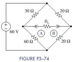
Expert Solution & Answer
Want to see the full answer?
Check out a sample textbook solution
Students have asked these similar questions
Thevenin voltage (Vth) and Thevenin resistance (Rth) according to the a-b ends of the circuit in the figure Find.
can you help me find a solution for future problems on how to solve in the future. Need to find the values of R3 and RT and find the total voltage.
Solve the given two circuits by your choice of approach and find.
a) Total Current and Total Resistance.
b) Voltage and current through R5.
R2
302
202 R1
200 R4 602R3
+
B1= 40V
R6
30n 40n3 R5
Chapter 3 Solutions
EBK THE ANALYSIS AND DESIGN OF LINEAR C
Ch. 3 - Formulate node-voltage equations for the circuit...Ch. 3 - (a) Formulate node-voltage equations for the...Ch. 3 - (a) Formulate node-voltage equations for the...Ch. 3 - Formulate node-voltage equations for the circuit...Ch. 3 - (a) Formulate node-voltage equations for the...Ch. 3 - Choose a ground wisely and formulate node-voltage...Ch. 3 - The following are a set of node-voltage equations;...Ch. 3 - Choose a ground wisely and formulate node-voltage...Ch. 3 - Formulate node-voltage equations for the circuit...Ch. 3 - Formulate node-voltage equations for the circuit...
Ch. 3 - (a) Formulate mesh-current equations for the...Ch. 3 - (a) Formulate mesh-current equations for the...Ch. 3 - (a) Formulate mesh-current equations for the...Ch. 3 - Prob. 3.16PCh. 3 - Formulate mesh-current equations for the circuit...Ch. 3 - For the circuit of figure P3-19 solve for iA,iB,...Ch. 3 - Formulate mesh-current equations for the circuit...Ch. 3 - The circuit in Figure P3-21 seems to require two...Ch. 3 - Formulate mesh-current equations for the circuit...Ch. 3 - Use simple engineering intuition to find the input...Ch. 3 - In Figure P3-24 all of the resistors are 1k and...Ch. 3 - Use Figure P3-24 and MATLAB to solve the following...Ch. 3 - Formulate mesh-current equations for the circuit...Ch. 3 - Find vO for the block diagram shown in figure...Ch. 3 - Design a voltage-divider circuit that will realize...Ch. 3 - Design a current-divider circuit that will realize...Ch. 3 - Using a single resistor, design a circuit that...Ch. 3 - Find the proportionality constant K=vO/vS for the...Ch. 3 - Find the proportionality constant K=iO/vS for the...Ch. 3 - Find the proportionality constant K=vO/iS for the...Ch. 3 - Find the proportionality constant K=iO/iS for the...Ch. 3 - Find the proportionality constant K=vO/vS for the...Ch. 3 - Use the unit output method to find K and vO in...Ch. 3 - Use the unit output method to find K and vO in...Ch. 3 - Use the unit output method to find K in Figure...Ch. 3 - Use the superposition principle to find vO in...Ch. 3 - Use the superposition principle to find vO in...Ch. 3 - Use the superposition principle to find vO in...Ch. 3 - (a) Use the superposition principle to find vO in...Ch. 3 - A linear circuit containing two sources drives a...Ch. 3 - A block diagram of a linear circuit is shown in...Ch. 3 - A certain linear circuit has four input voltages...Ch. 3 - When the current source is turned off in the...Ch. 3 - For the circuit in Figure P3—51, find the Thévenin...Ch. 3 - For the circuit in Figure P3—52, find the Thévenin...Ch. 3 - For the circuit of Figure P3—53, find the Thévenin...Ch. 3 - Find the Thévenin or Norton equivalent circuit...Ch. 3 - Find the Thévenin or Norton equivalent circuit...Ch. 3 - Find the Thévenin equivalent circuit seen by RL in...Ch. 3 - Find the Norton equivalent seen by RL in Figure...Ch. 3 - You need to determine the Thévenin equivalent...Ch. 3 - Find the Thévenin equivalent seen by RL in figure...Ch. 3 - The purpose of this problem is to use Thévenin...Ch. 3 - The circuit in Figure P3-62 was solved earlier...Ch. 3 - Assume that Figure P3-63 represents a model of the...Ch. 3 - The iv characteristic of the active circuit...Ch. 3 - You have successfully completed the first course...Ch. 3 - The Thévenin equivalent parameters of a practical...Ch. 3 - Use a sequence of source transformations to find...Ch. 3 - The circuit in Figure P3-68 provides power to a...Ch. 3 - A nonlinear resistor is connected across a...Ch. 3 - Prob. 3.71PCh. 3 - Find the Norton equivalent seen by RL in Figure...Ch. 3 - Find the Thévenin equivalent seen by RL in Figure...Ch. 3 - Find the Thévenin equivalent seen by RL in Figure...Ch. 3 - For the circuit of Figure P3-75, find the value of...Ch. 3 - For the circuit of Figure P3-76, find the value of...Ch. 3 - The resistance R in Figure P3-77 is adjusted until...Ch. 3 - When a 5-k resistor is connected across a...Ch. 3 - Find the value of R in the circuit of Figure P3-79...Ch. 3 - For the circuit of Figure P3-80, find the value of...Ch. 3 - A 1-k load needs 10 mA to operate correctly....Ch. 3 - A practical source delivers 25 mA to a load. The...Ch. 3 - A 10-V source is shown in Figure P3-83 that is...Ch. 3 - (a)Select RL and design an interface circuit for...Ch. 3 - The source in Figure P3-85 has a 100-mA output...Ch. 3 - Figure P3-86 shows an interface circuit connecting...Ch. 3 - Prob. 3.87PCh. 3 - In this problem, you will design two interface...Ch. 3 - Two teams are competing to design the interface...Ch. 3 - The bridge-T attenuation pad shown in FigureP3-90...Ch. 3 - Design two interface circuits in Figure P3-91 so...Ch. 3 - Design the interface circuit in Figure P3-91 so...Ch. 3 - Design the interface circuit in Figure P3-93 so...Ch. 3 - It is claimed that both interface circuits in...Ch. 3 - Audio Speaker Resistance-Matching Network A...Ch. 3 - Interface Circuit Design Using no more than three...Ch. 3 - Battery Design A satellite requires a battery with...Ch. 3 - Design Interface Competition The output of a...Ch. 3 - Prob. 3.106IP
Knowledge Booster


Learn more about
Need a deep-dive on the concept behind this application? Look no further. Learn more about this topic, electrical-engineering and related others by exploring similar questions and additional content below.Similar questions
- Consider the circuit diagram below. Solve for the current values and directions through R₁ and R4, and the voltage drop across R3 using mesh analysis. You may consider redrawing the circuit at the end of your analysis to better demonstrate polarities. Show your work and use Matlab to solve the system of equations that you generate. Be sure to include the commands you used in Matlab as part of your analysis. You must also use CircuitJS to verify your result. Attach an exported image or screen shot of your circuit from CircuitJS with the current and voltage "shown" (colors are shown on the diagram). E1 5V R1 1kΩ R2 5k Ω E2 20V R4 2k www R3 3Κ Ω R5 1kΩarrow_forwardIn the circuit model shown, for R1=9, R2=62, R3=7, R4=62, R5=68, R6=6 & Vab = 15 v, find the following: a R3 R4 R5 R1 R2 R6 Rea Req at terminals a-b= i= V= 0.0.0arrow_forwardcan someone help me with this problem and show me how to get it done step by step write a complete set of node voltage equatiosn that can be used to solve the circuit belowarrow_forward
- Find the equation for calculating what impedance R2 needs to have to obtain a “null measurement” at the voltmeter. Report the value of R2.arrow_forward8-13 E (a) Formulate mesh-current equations for the cir- cuit in Figure P3-13. (b) Formulate node-voltage equations for the circuit in Figure P3-13. (c) Which set of equations would be easier to solve? Why? (d) Using MATLAB, find , and i, in terms of the mesh- current variables. SSarrow_forwardUse the principles of superposition to find the current going through R3.arrow_forward
- identify the minterms that corresponds to the f and d below. Please be sure you know how to solve correctly and show work. I will also provide an image that states what the answer is without showing work I need to see work and explained how to get there. f=b'c'd' + abd' + abd d=a'c'd + b'cd'arrow_forwardRA R3 V2 D. R2 R1 For the above circuit, select ALL the extraordinary nodes that are part of a quasi-supernode. If there are none then select NONE. Note: a supernode is not a quasi-supernode. O NONE B. ODOarrow_forwardFor R1=10, R2=5, R3=15, R4=19, R5=4, R6=10, R7=8 and V1=140 V in the Figure, find the following: R1 R7 R4 ŽR2 V1 R6 3R3 ŽR5 ig= and then use current division to find i0=arrow_forward
- Can you please solve this circuit using MATLABarrow_forwardCreate a code from this circuit, use Verilog Structural Descriptionarrow_forwardConsider the circuit diagram below. Solve for the current values and directionsthrough R1 and R4, and the voltage drop across R3 using mesh analysis. You mayconsider redrawing the circuit at the end of your analysis to better demonstratepolarities. Show your work and use Matlab to solve the system of equations thatyou generate. Be sure to include the commands you used in Matlab as part ofyour analysis. You must also use CircuitJS to verify your result. Attach anexported image or screen shot of your circuit from CircuitJS with the current andvoltage “shown” (colors are shown on the diagram)arrow_forward
arrow_back_ios
SEE MORE QUESTIONS
arrow_forward_ios
Recommended textbooks for you
 Introductory Circuit Analysis (13th Edition)Electrical EngineeringISBN:9780133923605Author:Robert L. BoylestadPublisher:PEARSON
 Delmar's Standard Textbook Of ElectricityElectrical EngineeringISBN:9781337900348Author:Stephen L. HermanPublisher:Cengage Learning
 Programmable Logic ControllersElectrical EngineeringISBN:9780073373843Author:Frank D. PetruzellaPublisher:McGraw-Hill Education
 Fundamentals of Electric CircuitsElectrical EngineeringISBN:9780078028229Author:Charles K Alexander, Matthew SadikuPublisher:McGraw-Hill Education
 Electric Circuits. (11th Edition)Electrical EngineeringISBN:9780134746968Author:James W. Nilsson, Susan RiedelPublisher:PEARSON
 Engineering ElectromagneticsElectrical EngineeringISBN:9780078028151Author:Hayt, William H. (william Hart), Jr, BUCK, John A.Publisher:Mcgraw-hill Education,
Introductory Circuit Analysis (13th Edition)
Electrical Engineering
ISBN:9780133923605
Author:Robert L. Boylestad
Publisher:PEARSON
Delmar's Standard Textbook Of Electricity
Electrical Engineering
ISBN:9781337900348
Author:Stephen L. Herman
Publisher:Cengage Learning
Programmable Logic Controllers
Electrical Engineering
ISBN:9780073373843
Author:Frank D. Petruzella
Publisher:McGraw-Hill Education
Fundamentals of Electric Circuits
Electrical Engineering
ISBN:9780078028229
Author:Charles K Alexander, Matthew Sadiku
Publisher:McGraw-Hill Education
Electric Circuits. (11th Edition)
Electrical Engineering
ISBN:9780134746968
Author:James W. Nilsson, Susan Riedel
Publisher:PEARSON
Engineering Electromagnetics
Electrical Engineering
ISBN:9780078028151
Author:Hayt, William H. (william Hart), Jr, BUCK, John A.
Publisher:Mcgraw-hill Education,
Thevenin's Theorem; Author: Neso Academy;https://www.youtube.com/watch?v=veAFVTIpKyM;License: Standard YouTube License, CC-BY