
Videos
The current through a
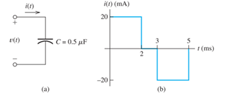
Figure P3.11

Learn your wayIncludes step-by-step video

Chapter 3 Solutions
Pearson eText for Electrical Engineering: Principles & Applications -- Instant Access (Pearson+)
Additional Engineering Textbook Solutions
Fundamentals of Applied Electromagnetics (7th Edition)
Introductory Circuit Analysis (13th Edition)
Starting Out with Java: From Control Structures through Data Structures (3rd Edition)
Engineering Mechanics: Statics
Starting Out with Java: From Control Structures through Data Structures (4th Edition) (What's New in Computer Science)
Automotive Technology: Principles, Diagnosis, and Service (5th Edition)


- If C1 = C2 = C3= 16 nF, calculate the equivalent capacitance, in nF, between points A and B in the diagram below. Give your answer to two significant figures. A. C₁ C₂ ... Barrow_forwardFind the equivalent inductance of the circuit in Figure Q3(a). Assume all inductors are 10 mH. a m L1arrow_forwardAcertain electric circuit has a resistor and a capacitor. The capacitor is initially charged to 100 V. When the power supply is detached, the capacitor voltage decays with time, as the following data table shows. Find a functional description of the capacitor voltage v as a function of time t. Plot the function and the data on the same plot.arrow_forward
- An inductor is "charged" to some value, then connected in series with a 1002 resistor and allowed to "discharge". A measurement of the potential difference across the resistor is shown in the figure below. Compute the time constant of the circuit, the inductance of the inductor, and the initial current through the inductor. 12 10 8 6 Potential across resistor (V) 2 0 0 0.0001 0.0002 0.0003 0.0004 0.0005 0.0006 0.0007 time (s)arrow_forwarda. As capacitor charges, describe the behavior of: i.current with time ii. the voltage across the resistor with time iii. capacitor voltage withtime Explain the reason for each behavior.arrow_forwardDetermine the equivalent inductance Leq between terminals a and b in Figure T3.5.arrow_forward
- 4. For the circuit shown in Figure...., determine (a) the total circuit capacitance, (b) the total energy in the circuit, and (c) the charges in the capacitors shown as C₁ and C₂. 2 F 2μF HH 2μF 2μF 2μF 2 μF C₁ HH HI 2 μF 50 V H 2μF C₂arrow_forwardIn the figure R1 When the switch is opened after having been closed for a long time, the current in the inductor drops from 1.00 A to 0.250 A in 0.200 s. What is the inductance of the inductor in mH? = 4.00 N , and R2 = 1.00 N. The inductor is ideal. %3D Şekildeki devrede R1 = 4.00 N , ve R2 = 1.00 N olarak verilmişlerdir. Solenoidin iç direnci yoktur. Anahtar uzun süre sonra kapalı kaldıktan sonra açılırsa solenoidden geçen akım 0,200 s içinde 1,00 A değerinden 0,250 A değerine düşmektedir. Solenoidin indüktansı mH cinsinden nedir? R1 S R2 L learrow_forwarda) The voltage across a 10 capacitance is ve = 150 sin( ......) volts and. Frequency equal to 50 Hz. Determine the current through the capacitor i and sketch its waveform. b) Define the term frequencyarrow_forward
- The current flowing through a 2-H inductance is shown in Figure P3.45. Sketch the voltage, power, and stored energy versus time.arrow_forwarda) The voltage across a 20uF capacitance is v. = 50 sin( at - 80) volts and Frequency equal to 100 Hz. Determine the current through the capacitor i and sketch its waveform. b) Define phasorarrow_forward. In the adjacent figure each of the two capacitors mounted in parallel has a value C,the resistor has a value R, and the power supply has value ɛ= 25 V. Upon closing thekey S the charging process of the two capacitors starts. The initial value of the electriccurrent was I0 = 25 mA, as shown in the table below, then the electric currentdecreased until it vanished at . The table below shows the values of the electriccurrent every two seconds as measured by the ammeter A.a) Determine the value R of the resistor in k ohm units.b)Plot the I-t graph (electric current versus time).c)Determine the circuit constant time from the I-t graph.d)Determine the value C of each capacitor in micro F units.e)Complete the table by evaluating the electric charge q(t) on eachcapacitor at the moments .arrow_forward
 Introductory Circuit Analysis (13th Edition)Electrical EngineeringISBN:9780133923605Author:Robert L. BoylestadPublisher:PEARSON
 Delmar's Standard Textbook Of ElectricityElectrical EngineeringISBN:9781337900348Author:Stephen L. HermanPublisher:Cengage Learning
 Programmable Logic ControllersElectrical EngineeringISBN:9780073373843Author:Frank D. PetruzellaPublisher:McGraw-Hill Education
 Fundamentals of Electric CircuitsElectrical EngineeringISBN:9780078028229Author:Charles K Alexander, Matthew SadikuPublisher:McGraw-Hill Education
 Electric Circuits. (11th Edition)Electrical EngineeringISBN:9780134746968Author:James W. Nilsson, Susan RiedelPublisher:PEARSON
 Engineering ElectromagneticsElectrical EngineeringISBN:9780078028151Author:Hayt, William H. (william Hart), Jr, BUCK, John A.Publisher:Mcgraw-hill Education,