
Pearson eText for Electrical Engineering: Principles & Applications -- Instant Access (Pearson+)
7th Edition
ISBN: 9780137562855
Author: Allan Hambley
Publisher: PEARSON+
expand_more
expand_more
format_list_bulleted
Videos
Textbook Question
Chapter 3, Problem 3.51P
A constant voltage of 10V is applied to a
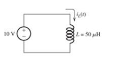
Figure P3 51
The current in the inductance at t = 0 is —100 mA. At what time I, does the current reach +100 mA?
Expert Solution & Answer
Want to see the full answer?
Check out a sample textbook solution
Students have asked these similar questions
In the figure R1
When the switch is opened after having been closed for a long time,
the current in the inductor drops from 1.00 A to 0.250 A in 0.200 s.
What is the inductance of the inductor in mH?
= 4.00 N , and R2
= 1.00 N. The inductor is ideal.
%3D
Şekildeki devrede R1 = 4.00 N , ve R2 = 1.00 N olarak verilmişlerdir.
Solenoidin iç direnci yoktur. Anahtar uzun süre sonra kapalı kaldıktan
sonra açılırsa solenoidden geçen akım 0,200 s içinde 1,00 A değerinden
0,250 A değerine düşmektedir. Solenoidin indüktansı mH cinsinden
nedir?
R1
S
R2
L
le
For the series-parallel inductor circuit shown in figure B19, answer the following questions.
2mH
4mH
SmH
3.5mH
8mH
8mH
n2mH
Figure B19
Determine the inductance, L value.
If E is the energy stored in inductor for current, I. Calculate the energy if the current
value is increased twice.
Q19. For the series-parallel inductor circuit shown in figure B19, answer the following questions.
L2
2mH
4mH
L3
L4
SMHS
5mH
3.5mH L6
8mH
L7
2mH
L3
4.5mH
e
Figure B19
Determine the inductance, L3 value.
ii) If E is the energy stored in inductor for current,
Calculate the energy if the current
value is increased twice.
Chapter 3 Solutions
Pearson eText for Electrical Engineering: Principles & Applications -- Instant Access (Pearson+)
Ch. 3 - What is a dielectric material? Give two examples.Ch. 3 - Briefly discuss how current can flow “through” a...Ch. 3 - What current flows through an ideal capacitor if...Ch. 3 - Describe the internal construction of capacitors.Ch. 3 - A voltage of 50 V appears across a 10F capacitor....Ch. 3 - A 2000F capacitor, initially charged to 100V, is...Ch. 3 - A 5F Capacitor ischarged to 1000 V. Determine the...Ch. 3 - The voltage across a 10F capacitor is given by v...Ch. 3 - The voltage across a 1F capacitor is given by...Ch. 3 - Prior to t = 0, a 100F capacitance is uncharged...
Ch. 3 - The current through a 0.5F capacitor is shown in...Ch. 3 - Determine the capacitor voltage, power, and stored...Ch. 3 - A current given by i(t)=Imcos(t) flows through a...Ch. 3 - The current through a 3F capacitor is shown in...Ch. 3 - A constant (dc) current i(t)=3 mA flows into a 50F...Ch. 3 - The energy stored in a 2F capacitor is 200 J and...Ch. 3 - At t=t0 the voltage across a certain capacitance...Ch. 3 - An unusual capacitor has a capacitance that is a...Ch. 3 - For a resistor, what resistance corresponds to a...Ch. 3 - Suppose we have a very large capacitance (ideally,...Ch. 3 - We want to store sufficient energy in a 001-F...Ch. 3 - A 100F capacitor has a voltage given by v(t)=1010...Ch. 3 - How are capacitances combined in series and in...Ch. 3 - Find the equivalent capacitance for each of the...Ch. 3 - Find the equivalent capacitance between terminals...Ch. 3 - A network has a 5F capacitance in series with the...Ch. 3 - What are the minimum and maximum values of...Ch. 3 - Two initially uncharged capacitors C1=15F and...Ch. 3 - Suppose that we are designing a cardiac pacemaker...Ch. 3 - Suppose that we have two 100F capacitors One is...Ch. 3 - Determine the capacitance of a parallel-plate...Ch. 3 - A 100-pF capacitor is constructed of parallel...Ch. 3 - We have a parallel-plate capacitor with plates of...Ch. 3 - Suppose that we have a 1000-pF parallel-plate...Ch. 3 - Two 1F capacitors have an initial voltage of 100 V...Ch. 3 - Prob. 3.36PCh. 3 - Prob. 3.37PCh. 3 - A parallel-plate capacitor is used as a vibration...Ch. 3 - A 0.1F capacitor has a parasitic series resistance...Ch. 3 - Prob. 3.40PCh. 3 - Briefly discuss how inductors are constructed.Ch. 3 - The current flowing through an inductor is...Ch. 3 - If the current through an ideal inductor is...Ch. 3 - Briefly discuss the fluid-flow analogy for an...Ch. 3 - The current flowing through a 2-H inductance is...Ch. 3 - The current flowing through a 100-mH inductance is...Ch. 3 - The current flowing through a 2-H inductance is...Ch. 3 - The voltage across a 2-H inductance is shown in...Ch. 3 - The voltage across a 10 H inductance is given by...Ch. 3 - A 2-H inductance has i(0) = 0 and v(t)=texp(t) for...Ch. 3 - A constant voltage of 10V is applied to a 50H...Ch. 3 - At t = 0, the current flowing in a 05-H inductance...Ch. 3 - The current through a 100-mH inductance is given...Ch. 3 - Prior to t= 0, the current in a 2-H inductance is...Ch. 3 - At t= 0, a constant 5-V voltage source is applied...Ch. 3 - Prob. 3.56PCh. 3 - Al t= 5 s, the energy stored in a 2-H inductor is...Ch. 3 - What value of inductance (having zero initial...Ch. 3 - To what circuit element does a very large...Ch. 3 - The voltage across an inductance L is given by...Ch. 3 - Discuss how inductances are combined in series and...Ch. 3 - Determine the equivalent inductance for each of...Ch. 3 - Find the equivalent inductance for each of the...Ch. 3 - What is the maximum inductance that can be...Ch. 3 - Suppose we want to combine (in series or in...Ch. 3 - Prob. 3.66PCh. 3 - Two inductances L1=1H and L2=2H are connected in...Ch. 3 - A 10-mH inductor has a parasitic series resistance...Ch. 3 - Draw the equivalent circuit for a real inductor,...Ch. 3 - Suppose that the equivalent circuit shown in...Ch. 3 - Consider the circuit shown in Figure P3.71 in...Ch. 3 - The circuit shown in Figure P3.72 has...Ch. 3 - Describe briefly the physical basis for mutual...Ch. 3 - The mutually coupled inductances in Figure P3.74...Ch. 3 - Repeat Problem P3.74 with the dot placed at the...Ch. 3 - a. Derive an expression for the equivalent...Ch. 3 - Consider the parallel inductors shown in Figure...Ch. 3 - Consider the mutually coupled inductors shown in...Ch. 3 - Mutually coupled inductances have...Ch. 3 - The current through a 200-mH inductance is given...Ch. 3 - A 1-H inductance has iL(0)=0 and vL(t)=texp(t) for...Ch. 3 - The current flowing through a 10F capacitor having...Ch. 3 - Determine the equivalent capacitance Ceq for...Ch. 3 - A certain parallel-plate capacitor has plate...Ch. 3 - A 2-mH inductance has iab=0.3sin(2000t)A . Find an...Ch. 3 - Determine the equivalent inductance Leq between...Ch. 3 - Given that vc(t)=10sin(1000t)V , find vs(t)in the...Ch. 3 - Prob. 3.7PTCh. 3 - The current flowing through a 20F capacitor having...
Additional Engineering Textbook Solutions
Find more solutions based on key concepts
Assume a telephone signal travels through a cable at two-thirds the speed of light. How long does it take the s...
Electric Circuits (10th Edition)
Design an ideal inverting op-amp circuit such that the voltage gain is Av=25 . The maximum current in any resis...
Microelectronics: Circuit Analysis and Design
With respect to the circuit in Fig. 5.90, (a) employ Thévenin’s theorem to determine the equivalent network see...
Loose Leaf for Engineering Circuit Analysis Format: Loose-leaf
The current source in the circuit shown generates the current pulse
Find (a) v (0); (b) the instant of time gr...
Electric Circuits. (11th Edition)
Explain the main function of each of the following major components of a PLC: a. Processor module (CPU) b. I/O ...
Programmable Logic Controllers
The voltage source of the circuit shown in Fig. P1.29 is given by s(t)=25cos(4104t45)(V). Obtain an expression ...
Fundamentals of Applied Electromagnetics (7th Edition)
Knowledge Booster


Learn more about
Need a deep-dive on the concept behind this application? Look no further. Learn more about this topic, electrical-engineering and related others by exploring similar questions and additional content below.Similar questions
- Three capacitors having capacitance values of 20F,40F, and 50F are connected in parallel to a 60 - Hz power line. An ammeter indicates a circuit current of 8.6 amperes. How much current is flowing through the 40F capacitor?arrow_forwardA0.5-µF capacitor has a voltage waveform v(t) as shown in Figure P3–7. Determine and plot the current waveform i(t). 3-7 v(t) FIGURE P3–7 60 V 40 V 2 6. 10 12 t, msarrow_forwardWhat do you think will happen to the current if the frequency is adjusted higher in the pure inductance experiment? and what will happen to the current if the frequency is adjusted lower in pure inductance experiment? explain why pleasearrow_forward
- Find the current through the inductor shown in Figure lb. (i/p is AC, consider results upto one decimal place). 1. 100 V 100 Hz 500 L=60H Figure lbarrow_forwardA 20-ohm resistor and a capacitor are connected in series with a battery of 60 volts. At t = 0, there is no charge on the capacitor. Find the capacitance if the current at t = 5 seconds is 3/e^s amperes. Ans. 0.05 Faradsarrow_forward3-10 A0.25-F capacitor has a current waveform i(t) as shown in Figure P3–10. Determine and plot the voltage waveform v(t) as a function of time. The capacitor is initially a and plot the voltage waveform v(t) as a function of time. The capacitor is imu uncharged. FIGURE P3-10 ilt) 4 A 6. -4 Aarrow_forward
- In the figure R1 When the switch is opened after having been closed for a long time, the current in the inductor drops from 1.00 A to 0.250 A in 0.200 s. = 4.00 N , and R2 = 1.00 N. The inductor is ideal. What is the inductance of the inductor in mH? = 1.00 N olarak verilmişlerdir. Şekildeki devrede R1 = 4.00 N , ve R2 Solenoidin iç direnci yoktur. Anahtar uzun süre sonra kapalı kaldıktan sonra açılırsa solenoidden geçen akım 0,200 s içinde 1,00 A değerinden 0,250 A değerine düşmektedir. Solenoidin indüktansı mH cinsinden nedir? %3D R S E -R2 Larrow_forwardWhat is the value of the induced voltage of the self-inductance when the rate of current is from 200 uA to 20 uA and the total time interval is 5 uS?arrow_forward4. For the circuit shown in Figure...., determine (a) the total circuit capacitance, (b) the total energy in the circuit, and (c) the charges in the capacitors shown as C₁ and C₂. 2 F 2μF HH 2μF 2μF 2μF 2 μF C₁ HH HI 2 μF 50 V H 2μF C₂arrow_forward
- Q1 (a) For the circuit in Figure Q1(a), the total charge, Q. is 0.0018 C. (i) Find the value of capacitance, C2 (ii) Calculate the voltage, Vi across capacitor C. (iii) Determine the charge, Qa stored in capacitor C4 C1 Qt +V- 40μF C3 C2 10F 10uF C4 90 V Figure Q1(a)arrow_forwardRefer to the circuit shown in Figure Assume that the inductor has a wire resistance of 0.2 Q and the resistor has a value of 250 Q. If a current of 3 A is flowing through the inductor, what will be the maximum induced voltage when the switch is opened? FIGURE The resistor helps prevent voltage spikes caused by the inductor. Switch Batteryarrow_forwardIn the figure ɛ = inductor is ideal. If the switch is closed for a long time, what is the current through the inductor. Give your answer in A. 10.0 V, R, = 4.00 N, and R2 = 1.00 N. The %3D %3Darrow_forward
arrow_back_ios
SEE MORE QUESTIONS
arrow_forward_ios
Recommended textbooks for you
 Delmar's Standard Textbook Of ElectricityElectrical EngineeringISBN:9781337900348Author:Stephen L. HermanPublisher:Cengage Learning
Delmar's Standard Textbook Of Electricity
Electrical Engineering
ISBN:9781337900348
Author:Stephen L. Herman
Publisher:Cengage Learning
Inductors Explained - The basics how inductors work working principle; Author: The Engineering Mindset;https://www.youtube.com/watch?v=KSylo01n5FY;License: Standard Youtube License