Design of Machinery
6th Edition
ISBN: 9781260431315
Author: Norton, Robert
Publisher: MCGRAW-HILL HIGHER EDUCATION
expand_more
expand_more
format_list_bulleted
Concept explainers
Videos
Textbook Question
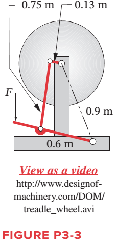
Chapter 3, Problem 3.14P
Figure P3-3 shows a treadle-operated grinding wheel driven by a fourbar linkage. Make a model of the linkage to any convenient scale. Find its minimum transmission angles from the model. Comment on its operation. Will it work? If so, explain how it does.
Expert Solution & Answer
Want to see the full answer?
Check out a sample textbook solution
Students have asked these similar questions
The following figure shows a treadle-operated grinding wheel driven by a four-bar linkage.Find the maximum and minimum transmission angles over its range of motion.
Figure below shows a four-bar linkage (non-scaled diagram) at an instant. The input
angle is equal to the output angle (02 - 04) and the transmission angle is 30°. The
input link is extended beyond joint B and an input force (Fin) is applied at the end of
it, while an output force is drawn from the midpoint of the output link. If an output
force of 30 N is desired from an input force of 10 N, how far the input link should be
extended, i.e., what is the distance from point B to the point where Fin is applied.
Fin
B
out
undefined
02
04
A.
Non-scaled diagram; AB = 10, CD=r4 = 30 (output), all in mm
Identify whether the following set of dimensions determines a Grashoff, Non-Grashoff or SpecialCase mechanism. If it is a Grashoff mechanism state what is kind of kinematic inversion it is
Chapter 3 Solutions
Design of Machinery
Ch. 3 - Define the following examples as path, motion, or...Ch. 3 - Design a fourbar Grashof crank-rocker for 90 of...Ch. 3 - Prob. 3.3PCh. 3 - Design a fourbar mechanism to give the two...Ch. 3 - Prob. 3.5PCh. 3 - Prob. 3.6PCh. 3 - Repeat Problem 3-2 with a quick-return time ratio...Ch. 3 - Design a sixbar drag link quick-return linkage for...Ch. 3 - Design a crank-shaper quick-return mechanism for a...Ch. 3 - Find the two cognates of the linkage in Figure...
Ch. 3 - Find the three equivalent geared fivebar linkages...Ch. 3 - Design a sixbar single-dwell linkage for a dwell...Ch. 3 - Design a sixbar double-dwell linkage for a dwell...Ch. 3 - Figure P3-3 shows a treadle-operated grinding...Ch. 3 - Figure P3-4 shows a non-Grashof fourbar linkage...Ch. 3 - Prob. 3.16PCh. 3 - Prob. 3.17PCh. 3 - Prob. 3.18PCh. 3 - Design a pin-jointed linkage that will guide the...Ch. 3 - Figure P3-6 shows a V-link off-loading mechanism...Ch. 3 - Prob. 3.21PCh. 3 - Prob. 3.22PCh. 3 - Figure P3-8 shows a fourbar linkage used in a...Ch. 3 - Prob. 3.24PCh. 3 - Prob. 3.25PCh. 3 - Prob. 3.26PCh. 3 - Prob. 3.27PCh. 3 - Prob. 3.28PCh. 3 - Prob. 3.29PCh. 3 - Prob. 3.30PCh. 3 - Design a Hoeken straight-line linkage to give...Ch. 3 - Design a Hoeken straight-line linkage to give...Ch. 3 - Prob. 3.33PCh. 3 - Prob. 3.34PCh. 3 - Prob. 3.35PCh. 3 - Find the Grashof condition, inversion, any limit...Ch. 3 - Prob. 3.37PCh. 3 - Prob. 3.38PCh. 3 - Prob. 3.39PCh. 3 - Draw the Roberts diagram and find the cognates of...Ch. 3 - Prob. 3.41PCh. 3 - Find the Grashof condition, any limit positions,...Ch. 3 - Prob. 3.43PCh. 3 - Prob. 3.44PCh. 3 - Prob. 3.45PCh. 3 - Prob. 3.46PCh. 3 - Prob. 3.47PCh. 3 - Prob. 3.48PCh. 3 - Prob. 3.49PCh. 3 - Prob. 3.50PCh. 3 - Prob. 3.51PCh. 3 - Prob. 3.52PCh. 3 - Prob. 3.53PCh. 3 - Prob. 3.54PCh. 3 - Prob. 3.55PCh. 3 - Prob. 3.56PCh. 3 - Prob. 3.57PCh. 3 - Prob. 3.58PCh. 3 - Prob. 3.59PCh. 3 - Prob. 3.60PCh. 3 - Prob. 3.61PCh. 3 - Prob. 3.62PCh. 3 - Prob. 3.63PCh. 3 - Prob. 3.64PCh. 3 - Prob. 3.65PCh. 3 - Prob. 3.66PCh. 3 - Design a fourbar Grashof crank-rocker for 120 of...Ch. 3 - Prob. 3.68PCh. 3 - Design a fourbar Grashof crank-rocker for 80 of...Ch. 3 - Design a sixbar drag link quick-return linkage for...Ch. 3 - Design a crank shaper quick-return mechanism for a...Ch. 3 - Design a sixbar, single-dwell linkage for a dwell...Ch. 3 - Design a sixbar, single-dwell linkage for a dwell...Ch. 3 - Prob. 3.74PCh. 3 - Using the method of Example 3-11, show that the...Ch. 3 - Prob. 3.76PCh. 3 - Prob. 3.77PCh. 3 - Prob. 3.78PCh. 3 - The first set of 10 coupler curves on page 1 of...Ch. 3 - Prob. 3.80PCh. 3 - Prob. 3.81PCh. 3 - Prob. 3.82PCh. 3 - Prob. 3.83PCh. 3 - Prob. 3.84PCh. 3 - Prob. 3.85PCh. 3 - Prob. 3.86PCh. 3 - Prob. 3.87PCh. 3 - The side view of the upper section of a...Ch. 3 - Design a fourbar mechanism to give the three...Ch. 3 - Design a fourbar mechanism to give the three...Ch. 3 - Design a fourbar Grashof crank-rocker for 60...Ch. 3 - Design a crank-shaper quick-return mechanism for a...Ch. 3 - Figure P3-22 shows a non-Grashof fourbar linkage...Ch. 3 - Prob. 3.94PCh. 3 - Design a fourbar Grashof crank-rocker for 80...Ch. 3 - Design a sixbar drag link quick-return linkage for...
Knowledge Booster


Learn more about
Need a deep-dive on the concept behind this application? Look no further. Learn more about this topic, mechanical-engineering and related others by exploring similar questions and additional content below.Similar questions
- Crank Rocker mechanism, Link 1= 177.8 mm; Link 2 = 228.6 mm; Link 3 = 76.2 mm and Link 4 = 203.2 mm. If the angular position of Link 2 is 85.22° find the possible angular positions of Link 3 and Link 4 using graphical method.arrow_forwardThe following figure shows a treadle-operated grinding wheel driven by a four-bar linkage. Find the toggle and limit positions.arrow_forwardDraw the kinematic diagram of the following mechanismarrow_forward
- Problem 4-6a The link lengths (a, b, c, d) and the value of 2 for a crank-rocker linkage are defined as 2, 7, 9, 6, 30°, respectively. Draw the scaled linkage. Find all possible solutions (both open and crossed) for angles 03 and 04 graphically. Орen B A LNCS 4 a GCS र 4 4" Crossed (This is not the scaled kinematic diagram.) Problem 4-7a Repeat Problem 4-6a except solve by the vector loop method.arrow_forward2- Figure (2) shows an epicyclic gear train suitable for lifting machine with the following particular: Gear A is the mounted on the motor shaft and the load spindle is attached to the arm 7. planet wheels C and Ci are compound. The number of teeth on wheels A and Ci are 20 The internal wheel B is fixed. A speed reduction of about 12 is required. Find the suitable number of teeth ror C and B and the exact value of speed ratio which these give. Z asarrow_forwardThe linkage in Figure P7-5b has 04A = O2A = 0.75 , AB = 1.5 , and AC = 1.2 in . The effective crank angle in the position shown is 77º and angle BAC = 30 ° . Find a3 , AA , AB , Ac for the position shown for m2 = 15 rad / sec and a2 = 10 rad / sec2 in the directions shown using an analytical method . ( Hint : Create an effective linkage for the position shown and analyze it as a pin - jointed fourbar . ) the linkage has a parallelogram form Assume rolling contact C 02 A 3 . B 02 02 Tarrow_forward
- 7- Figure P6-28 shows a quick-return mechanism with dimensions. Calculate the velocities of points A, B, and C and the velocity of slip for the position shown. ₂ = 10 rad/s CCW. L₂=1.00 in L4=4.76 Ls=4.55 0₂ = 99⁰ 040₂ = 1.69 @ 15.5° 00₂ X 2.86 inarrow_forwardIdentify whether the following set of dimensions determines a Grashoff, Non-Grashoff or Special Case mechanism. If it is a Grashoff mechanism state what is kind of kinematic inversion it is (ex. Crank-Rocker, etc.). Provide necessary computationsarrow_forward1. Find a combination of link lengths where motion of a point on output link is one quarter of a circle. 2. Find the value of all 0, 0, 0, and y in open and close configuration Read the value of link lengths and the input angle 8., then use the formulae given below to calculate the value of unknowns 03, 0, and y K₁ = = K₂= d K2 K3 = a²-b²+c²+d² 2ac A = cos 0₂ - K₁ - K₂ cos 0₂ + K3 B = -2 sin 0₂ C = K₁ (K₂ + 1) cos 02 + K3 -B± √B²-4AC 2A 0412 = 2tan-1 d K₁ = — K5 = c²d²a²-6² 2ab D = cos 0₂ - K₁ - K4 cos 0₂ + K5 E = -2 sin 0₂ FK₁+ (K₁ - 1) cos 02 +K5 0312 2 tan-1 (-E± -E± √E²4DF 2D Y = 04-03arrow_forward
- Evaluate the 3-DOF wrist as shown in Figure 2, use the conventional method to determine 1. Linear velocity and 2. Angular velocity NOTE: for JOINT 3 ( 03 ) only Connected to robot Figure 2: Wrist assembly The known position and orientation of the end of the arm point is. [-C,S2C3 + S1S3 C;S2S3 +S1C3 |-S;S2C3 – C,S3 S,S2S3 + C,C3 -C2S3 C,C2 S,C2 S2 °T3=°T;'T2?T3= C2C3 [G 0 S, 0 S, 0 -G 0 °T 1 0 0 1 -S2 0 C, 0° C2 0 S, 0 'T2 1 1 [C3 -S3 0 07 S3 C3 0 0 2T3= 1 0 0 0 1 00010 IIarrow_forwardSelect one simple mechanism (4 links) and explain the following with regards to the selected mechanism. i. Kinematic pairs based on nature of contact. ii. Kinematic pairs based on nature of relative motion. iii. Degrees of freedom. iv. Possible inversions and applicationsarrow_forwardPROBLEM Draw the kinematic diagram of the given mechanism below. The ends of the two handles and the end of the bucket should be identified as points of interest. Calculate its mobility as well in terms of the number of degrees of freedom. FIGURE SOLUTION PLATE NO IA: KINEMATIC DIAGRAMS AND DEGREES OF FREEDOM SCOREarrow_forward
arrow_back_ios
SEE MORE QUESTIONS
arrow_forward_ios
Recommended textbooks for you
 Elements Of ElectromagneticsMechanical EngineeringISBN:9780190698614Author:Sadiku, Matthew N. O.Publisher:Oxford University Press
 Mechanics of Materials (10th Edition)Mechanical EngineeringISBN:9780134319650Author:Russell C. HibbelerPublisher:PEARSON
 Thermodynamics: An Engineering ApproachMechanical EngineeringISBN:9781259822674Author:Yunus A. Cengel Dr., Michael A. BolesPublisher:McGraw-Hill Education
 Control Systems EngineeringMechanical EngineeringISBN:9781118170519Author:Norman S. NisePublisher:WILEY
 Mechanics of Materials (MindTap Course List)Mechanical EngineeringISBN:9781337093347Author:Barry J. Goodno, James M. GerePublisher:Cengage Learning
 Engineering Mechanics: StaticsMechanical EngineeringISBN:9781118807330Author:James L. Meriam, L. G. Kraige, J. N. BoltonPublisher:WILEY
Elements Of Electromagnetics
Mechanical Engineering
ISBN:9780190698614
Author:Sadiku, Matthew N. O.
Publisher:Oxford University Press
Mechanics of Materials (10th Edition)
Mechanical Engineering
ISBN:9780134319650
Author:Russell C. Hibbeler
Publisher:PEARSON
Thermodynamics: An Engineering Approach
Mechanical Engineering
ISBN:9781259822674
Author:Yunus A. Cengel Dr., Michael A. Boles
Publisher:McGraw-Hill Education
Control Systems Engineering
Mechanical Engineering
ISBN:9781118170519
Author:Norman S. Nise
Publisher:WILEY
Mechanics of Materials (MindTap Course List)
Mechanical Engineering
ISBN:9781337093347
Author:Barry J. Goodno, James M. Gere
Publisher:Cengage Learning
Engineering Mechanics: Statics
Mechanical Engineering
ISBN:9781118807330
Author:James L. Meriam, L. G. Kraige, J. N. Bolton
Publisher:WILEY
Power Transmission; Author: Terry Brown Mechanical Engineering;https://www.youtube.com/watch?v=YVm4LNVp1vA;License: Standard Youtube License