
POWER SYS. ANALYSIS+DESIGN
6th Edition
ISBN: 9780357700907
Author: Glover
Publisher: INTER CENG
expand_more
expand_more
format_list_bulleted
Concept explainers
Videos
Textbook Question
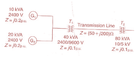
Chapter 3, Problem 3.28P
For the system shown in Figure 3.34. draw an impedance diagram in per unit by choosing 100 kVA to be the base kVA and 2400 V as the base voltage for the generators.
Expert Solution & Answer

Trending nowThis is a popular solution!

Students have asked these similar questions
Consider the three single-phase two-winding transformers shown in Figure. 3. The
high-voltage windings are connected in Y.
(a) For the low-voltage side, connect the windings in A, and label the terminals a,
b, and c in accordance with the American standard.
(b) Relabel the terminals a', b', and c' such that VAN is 90° out of phase with V₂'b'
for positive sequence.
DI
H₂
Figure. 3: Three-Winding Transformer
e = 0
Q1: What does happen if we change two currents?
a.
Q2: What does happen if we have a three-phase four poles machine?
Q3: What does happen if we have a two-phase two poles machine?
e = 0
Q4: What does happen if we apply a capacitance in phase b and then use same
voltage for both phase.
Dr. Ali Ki. pw --
What are FACTS (Flexible Alternating Current Transmission Systems), and how do they improve the control and efficiency of power transmission?
Chapter 3 Solutions
POWER SYS. ANALYSIS+DESIGN
Ch. 3 - The Ohms law for the magnetic circuit states that...Ch. 3 - For an ideal transformer, the efficiency is (a) 0...Ch. 3 - For an ideal 2-winding transformer, the...Ch. 3 - An ideal transformer has no real or reactive power...Ch. 3 - For an ideal 2-winding transformer, an impedance...Ch. 3 - Consider Figure 3.4. For an ideal phase-shifting...Ch. 3 - Consider Figure 3.5. Match the following, those on...Ch. 3 - The units of admittance, conductance, and...Ch. 3 - Match the following: (i) Hysteresis loss (a) Can...Ch. 3 - For large power transformers rated more than 500...
Ch. 3 - For a short-circuit test on a 2-winding...Ch. 3 - The per-unit quantity is always dimensionless. (a)...Ch. 3 - Consider the adopted per-unit system for the...Ch. 3 - The ideal transformer windings are eliminated from...Ch. 3 - To convert a per-unit impedance from old to new...Ch. 3 - In developing per-unit circuits of systems such as...Ch. 3 - Prob. 3.17MCQCh. 3 - Prob. 3.18MCQCh. 3 - With the American Standard notation, in either a...Ch. 3 - Prob. 3.20MCQCh. 3 - In order to avoid difficulties with third-harmonic...Ch. 3 - Does an open connection permit balanced...Ch. 3 - Does an open- operation, the kVA rating compared...Ch. 3 - It is stated that (i) balanced three-phase...Ch. 3 - In developing per-unit equivalent circuits for...Ch. 3 - In per-unit equivalent circuits of practical...Ch. 3 - Prob. 3.27MCQCh. 3 - Prob. 3.28MCQCh. 3 - For developing per-unit equivalent circuits of...Ch. 3 - Prob. 3.30MCQCh. 3 - Prob. 3.31MCQCh. 3 - Prob. 3.32MCQCh. 3 - The direct electrical connection of the windings...Ch. 3 - Consider Figure 3.25 of the text for a transformer...Ch. 3 - (a) An ideal single-phase two-winding transformer...Ch. 3 - An ideal transformer with N1=1000andN2=250 is...Ch. 3 - Consider an ideal transformer with...Ch. 3 - A single-phase 100-kVA,2400/240-volt,60-Hz...Ch. 3 - Prob. 3.5PCh. 3 - Prob. 3.6PCh. 3 - Consider a source of voltage v(t)=102sin(2t)V,...Ch. 3 - Prob. 3.8PCh. 3 - Prob. 3.9PCh. 3 - A single-phase step-down transformer is rated...Ch. 3 - For the transformer in Problem 3.10. The...Ch. 3 - Prob. 3.12PCh. 3 - A single-phase 50-kVA,2400/240-volt,60-Hz...Ch. 3 - A single-phase 50-kVA,2400/240-volt,60-Hz...Ch. 3 - Rework Problem 3.14 if the transformer is...Ch. 3 - A single-phase, 50-kVA,2400/240-V,60-Hz...Ch. 3 - The transformer of Problem 3.16 is supplying a...Ch. 3 - Using the transformer ratings as base quantities,...Ch. 3 - Using the transformer ratings as base quantities....Ch. 3 - Using base values of 20 kVA and 115 volts in zone...Ch. 3 - Prob. 3.21PCh. 3 - A balanced Y-connected voltage source with...Ch. 3 - Figure 3.32 shows the oneline diagram of a...Ch. 3 - For Problem 3.18, the motor operates at full load,...Ch. 3 - Consider a single-phase electric system shown in...Ch. 3 - A bank of three single-phase transformers, each...Ch. 3 - A three-phase transformer is rated...Ch. 3 - For the system shown in Figure 3.34. draw an...Ch. 3 - Consider three ideal single-phase transformers...Ch. 3 - Reconsider Problem 3.29. If Va,VbandVc are a...Ch. 3 - Prob. 3.31PCh. 3 - Determine the positive- and negative-sequence...Ch. 3 - Consider the three single-phase two-winding...Ch. 3 - Three single-phase, two-winding transformers, each...Ch. 3 - Consider a bank of this single-phase two-winding...Ch. 3 - Three single-phase two-winding transformers, each...Ch. 3 - Three single-phase two-winding transformers, each...Ch. 3 - Consider a three-phase generator rated...Ch. 3 - The leakage reactance of a three-phase,...Ch. 3 - Prob. 3.40PCh. 3 - Consider the single-line diagram of the power...Ch. 3 - For the power system in Problem 3.41, the...Ch. 3 - Three single-phase transformers, each rated...Ch. 3 - A 130-MVA,13.2-kV three-phase generator, which has...Ch. 3 - Figure 3.39 shows a oneline diagram of a system in...Ch. 3 - The motors M1andM2 of Problem 3.45 have inputs of...Ch. 3 - Consider the oneline diagram shown in Figure 3.40....Ch. 3 - With the same transformer banks as in Problem...Ch. 3 - Consider the single-Line diagram of a power system...Ch. 3 - A single-phase three-winding transformer has the...Ch. 3 - The ratings of a three-phase three-winding...Ch. 3 - Prob. 3.52PCh. 3 - The ratings of a three-phase, three-winding...Ch. 3 - An infinite bus, which is a constant voltage...Ch. 3 - A single-phase l0-kVA,2300/230-volt,60-Hz...Ch. 3 - Three single-phase two-winding transformers, each...Ch. 3 - A two-winding single-phase transformer rated...Ch. 3 - A single-phase two-winding transformer rated...Ch. 3 - Prob. 3.59PCh. 3 - PowerWorid Simulator case Problem 3_60 duplicates...Ch. 3 - Rework Example 3.12 for a+10 tap, providing a 10...Ch. 3 - A 23/230-kV step-up transformer feeds a...Ch. 3 - The per-unit equivalent circuit of two...Ch. 3 - Reconsider Problem 3.64 with the change that now...Ch. 3 - What are the advantages of correctly specifying a...Ch. 3 - Why is it important to reduce the moisture within...Ch. 3 - What should be the focus of transformer preventive...
Knowledge Booster


Learn more about
Need a deep-dive on the concept behind this application? Look no further. Learn more about this topic, electrical-engineering and related others by exploring similar questions and additional content below.Similar questions
- Three single-phase two-winding transformers, each rated 3kVA,220/110volts,60Hz, with a 0.10 per-unit leakage reactance, are connected as a three-phase extended autotransformer bank, as shown in Figure 3.36(c). The low-voltage winding has a 110 volt rating. (a) Draw the positive-sequence phasor diagram and show that the high-voltage winding has a 479.5 volt rating. (b) A three-phase load connected to the low-voltage terminals absorbs 6 kW at 110 volts and at 0.8 power factor lagging. Draw the per-unit impedance diagram and calculate the voltage and current at the high-voltage terminals. Assume positive-sequence operation.arrow_forwardConsider the three single-phase two-winding transformers shown in Figure 3.37. The high-voltage windings are connected in Y. (a) For the low-voltage side, connect the windings in , place the polarity marks, and label the terminals a, b, and c in accordance with the American standard. (b) Relabel the terminals a, b, and c such that VAN is 90 out of phase with Va for positive sequence.arrow_forwardThe reactance of a generator is given as 0.25 per-unit based on the generator’s of 18 kV, 500 MVA. Find its per-unit reactance on a base of 20 kV, 100 MVA. a. 0.0505 b. 0.0605 c. 0.0405 d. 0.0606arrow_forward
- 8 = 0 Q1: What does happen if we change two currents? Q2: What does happen if we have a three-phase four poles machine? a Q3: What does happen if we have a two-phase two poles machine? Q4: What does happen if we apply a capacitance in phase b and then use same voltage for both phase. Dr. Ali K....p. . --arrow_forwardpls write the solution in paperarrow_forwardDescribe the On-load and No-load in transformersarrow_forward
- The one-line diagram of a simple power system is shown in Figure below. The neutral of each generator is grounded through a current-limiting reactor of 0.25/3 per unit on a 100-MVA base. The system data expressed in per unit on a common 100-MVA base is tabulated below. The generators are running on no-load at their rated voltage and rated frequency with their emfs in phase. G Stark Item Base MVA Voltage Rating X' x² 20 kV 20 kV 20/220 kV 20/220 kV 100 0.05 0.15 0.15 0.10 0.10 220 kV 0.125 0.125 0.30 0.15 0.25 025 0.7125 0.15 100 100 0.15 0.05 0.10 0.10 0.10 100 0.10 100 100 Lu La 220 kV 0.15 220 kV 0.35 100 A balanced three-phase fault at bus 3 through a fault impedance Zf= jo.I per unit. The magnitude of the fault current in amperes in phase b for this fault is: Select one: A. 345.3 B. 820.1 C. 312500 3888888 产产arrow_forwardConsider the oneline diagram shown in Figure 3.40. The three-phase transformer bank is made up of three identical single-phase transformers, each specified by X1=0.24 (on the low-voltage side), negligible resistance and magnetizing current, and turns ratio =N2/N1=10. The transformer bank is delivering 100 MW at 0.8 p.f. lagging to a substation bus whose voltage is 230 kV. (a) Determine the primary current magnitude, primary voltage (line-to-line) magnitude, and the three-phase complex power supplied by the generator. Choose the line-to-neutral voltage at the bus, Va as the reference Account for the phase shift, and assume positive-sequence operation. (b) Find the phase shift between the primary and secondary voltages.arrow_forwardDetermine the positive- and negative-sequence phase shifts for the three- phase transformers shown in Figure 3.36.arrow_forward
- Consider a single-phase electric system shown in Figure 3.33. Transformers are rated as follows: XY15MVA,13.8/138kV, leakage reactance 10 YZ15MVA,138/69kV, leakage reactance 8 With the base in circuit Y chosen as 15MVA,138kV determine the per-unit impedance of the 500 resistive load in circuit Z, referred to circuits Z, Y, and X. Neglecting magnetizing currents, transformer resistances, and line impedances, draw the impedance diagram in per unit.arrow_forwardThe per-unit equivalent circuit of two transformers Ta and Tb connected in parallel, with the same nominal voltage ratio and the same reactan of 0.1 per unit on the same base, is shown in Figure 3.43. Transformer Tb has a voltage-magnitude step-up toward the load of 1.05 times that of Ta (that is, the tap on the secondary winding of Tb is set to 1.05). The load is represented by 0.8+j0.6 per unit at a voltage V2=1.0/0 per unit. Determine the complex power in per unit transmitted to the load through each transformer, comment on how the transformers share the real and reactive powers.arrow_forwardConsider three ideal single-phase transformers (with a voltage gain of ) put together as three-phase bank as shown in Figure 3.35. Assuming positive-sequence voltages for Va,Vb, and Vc find Va,Vb, and VC. in terms of Va,Vb, and Vc, respectively. (a) Would such relationships hold for the line voltages as well? (b) Looking into the current relationships, express IaIb and Ic in terms of IaIb and Ic respectively. (C) Let S and S be the per-phase complex power output and input. respectively. Find S in terms of S.arrow_forward
arrow_back_ios
SEE MORE QUESTIONS
arrow_forward_ios
Recommended textbooks for you
 Power System Analysis and Design (MindTap Course ...Electrical EngineeringISBN:9781305632134Author:J. Duncan Glover, Thomas Overbye, Mulukutla S. SarmaPublisher:Cengage Learning
Power System Analysis and Design (MindTap Course ...
Electrical Engineering
ISBN:9781305632134
Author:J. Duncan Glover, Thomas Overbye, Mulukutla S. Sarma
Publisher:Cengage Learning
TRANSFORMERS - What They Are, How They Work, How Electricians Size Them; Author: Electrician U;https://www.youtube.com/watch?v=tXPy4OE7ApE;License: Standard Youtube License