
Mastering Engineering with Pearson eText -- Standalone Access Card -- for Electrical Engineering: Principles & Applications
7th Edition
ISBN: 9780134486970
Author: Allan R. Hambley
Publisher: PEARSON
expand_more
expand_more
format_list_bulleted
Concept explainers
Videos
Textbook Question
Chapter 3, Problem 3.35P
Two
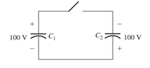
Figure P3.35
Expert Solution & Answer

Trending nowThis is a popular solution!

Students have asked these similar questions
Determine the equivalent capacitance of each of the circuits in the figure shown.
Note: I leave the image of the exercises in Spanish, but it is easy to understand.
Also in the other image is the correct final answer, for checking.
IMPORTANT:Please, preferably the procedure should be digital, not on paper.This way I understand better.I would appreciate it very much!
Refer to the diagram below. Compute the total capacitance, voltage and charge across each capacitor given that the total voltage is 120V. Please help, I've been getting ridiculously long decimal values and I don't know what to do.
A. Find the equivalent capacitance of the combination shown in the figure. (C2 = 2µF, C3 = 3µF)
B. Determine the charge on each capacitor, if there is a potential difference of 900V
C. Determine the voltages across each capacitor
Chapter 3 Solutions
Mastering Engineering with Pearson eText -- Standalone Access Card -- for Electrical Engineering: Principles & Applications
Ch. 3 - What is a dielectric material? Give two examples.Ch. 3 - Briefly discuss how current can flow “through” a...Ch. 3 - What current flows through an ideal capacitor if...Ch. 3 - Describe the internal construction of capacitors.Ch. 3 - A voltage of 50 V appears across a 10F capacitor....Ch. 3 - A 2000F capacitor, initially charged to 100V, is...Ch. 3 - A 5F Capacitor ischarged to 1000 V. Determine the...Ch. 3 - The voltage across a 10F capacitor is given by v...Ch. 3 - The voltage across a 1F capacitor is given by...Ch. 3 - Prior to t = 0, a 100F capacitance is uncharged...
Ch. 3 - The current through a 0.5F capacitor is shown in...Ch. 3 - Determine the capacitor voltage, power, and stored...Ch. 3 - A current given by i(t)=Imcos(t) flows through a...Ch. 3 - The current through a 3F capacitor is shown in...Ch. 3 - A constant (dc) current i(t)=3 mA flows into a 50F...Ch. 3 - The energy stored in a 2F capacitor is 200 J and...Ch. 3 - At t=t0 the voltage across a certain capacitance...Ch. 3 - An unusual capacitor has a capacitance that is a...Ch. 3 - For a resistor, what resistance corresponds to a...Ch. 3 - Suppose we have a very large capacitance (ideally,...Ch. 3 - We want to store sufficient energy in a 001-F...Ch. 3 - A 100F capacitor has a voltage given by v(t)=1010...Ch. 3 - How are capacitances combined in series and in...Ch. 3 - Find the equivalent capacitance for each of the...Ch. 3 - Find the equivalent capacitance between terminals...Ch. 3 - A network has a 5F capacitance in series with the...Ch. 3 - What are the minimum and maximum values of...Ch. 3 - Two initially uncharged capacitors C1=15F and...Ch. 3 - Suppose that we are designing a cardiac pacemaker...Ch. 3 - Suppose that we have two 100F capacitors One is...Ch. 3 - Determine the capacitance of a parallel-plate...Ch. 3 - A 100-pF capacitor is constructed of parallel...Ch. 3 - We have a parallel-plate capacitor with plates of...Ch. 3 - Suppose that we have a 1000-pF parallel-plate...Ch. 3 - Two 1F capacitors have an initial voltage of 100 V...Ch. 3 - Prob. 3.36PCh. 3 - Prob. 3.37PCh. 3 - A parallel-plate capacitor is used as a vibration...Ch. 3 - A 0.1F capacitor has a parasitic series resistance...Ch. 3 - Prob. 3.40PCh. 3 - Briefly discuss how inductors are constructed.Ch. 3 - The current flowing through an inductor is...Ch. 3 - If the current through an ideal inductor is...Ch. 3 - Briefly discuss the fluid-flow analogy for an...Ch. 3 - The current flowing through a 2-H inductance is...Ch. 3 - The current flowing through a 100-mH inductance is...Ch. 3 - The current flowing through a 2-H inductance is...Ch. 3 - The voltage across a 2-H inductance is shown in...Ch. 3 - The voltage across a 10 H inductance is given by...Ch. 3 - A 2-H inductance has i(0) = 0 and v(t)=texp(t) for...Ch. 3 - A constant voltage of 10V is applied to a 50H...Ch. 3 - At t = 0, the current flowing in a 05-H inductance...Ch. 3 - The current through a 100-mH inductance is given...Ch. 3 - Prior to t= 0, the current in a 2-H inductance is...Ch. 3 - At t= 0, a constant 5-V voltage source is applied...Ch. 3 - Prob. 3.56PCh. 3 - Al t= 5 s, the energy stored in a 2-H inductor is...Ch. 3 - What value of inductance (having zero initial...Ch. 3 - To what circuit element does a very large...Ch. 3 - The voltage across an inductance L is given by...Ch. 3 - Discuss how inductances are combined in series and...Ch. 3 - Determine the equivalent inductance for each of...Ch. 3 - Find the equivalent inductance for each of the...Ch. 3 - What is the maximum inductance that can be...Ch. 3 - Suppose we want to combine (in series or in...Ch. 3 - Prob. 3.66PCh. 3 - Two inductances L1=1H and L2=2H are connected in...Ch. 3 - A 10-mH inductor has a parasitic series resistance...Ch. 3 - Draw the equivalent circuit for a real inductor,...Ch. 3 - Suppose that the equivalent circuit shown in...Ch. 3 - Consider the circuit shown in Figure P3.71 in...Ch. 3 - The circuit shown in Figure P3.72 has...Ch. 3 - Describe briefly the physical basis for mutual...Ch. 3 - The mutually coupled inductances in Figure P3.74...Ch. 3 - Repeat Problem P3.74 with the dot placed at the...Ch. 3 - a. Derive an expression for the equivalent...Ch. 3 - Consider the parallel inductors shown in Figure...Ch. 3 - Consider the mutually coupled inductors shown in...Ch. 3 - Mutually coupled inductances have...Ch. 3 - The current through a 200-mH inductance is given...Ch. 3 - A 1-H inductance has iL(0)=0 and vL(t)=texp(t) for...Ch. 3 - The current flowing through a 10F capacitor having...Ch. 3 - Determine the equivalent capacitance Ceq for...Ch. 3 - A certain parallel-plate capacitor has plate...Ch. 3 - A 2-mH inductance has iab=0.3sin(2000t)A . Find an...Ch. 3 - Determine the equivalent inductance Leq between...Ch. 3 - Given that vc(t)=10sin(1000t)V , find vs(t)in the...Ch. 3 - Prob. 3.7PTCh. 3 - The current flowing through a 20F capacitor having...
Knowledge Booster


Learn more about
Need a deep-dive on the concept behind this application? Look no further. Learn more about this topic, electrical-engineering and related others by exploring similar questions and additional content below.Similar questions
- Determine the equivalent capacitance of each of the circuits in the figure shown. Note: I leave the image of the exercises in Spanish, but it is easy to understand. Also in the other image is the correct final answer, for checking.arrow_forwardCalculate the equivalent inductance of the circuit in Figure Q3(b). Assume allinductors are 20 mH.arrow_forwardIllustrate 3 simple capacitors and label it's important parts. Pls include a picturearrow_forward
- In this circuit, the capacitance of the capacitor is 1 F, the resistance of the resistor is 1 Ohm, and the battery voltage = 1 V. When the switch is moved from a to b at time t=0, the amount of electric charge stored in the capacitor at t=1 second is approx.. .C.arrow_forwardCapacitance= 4uF , Hence time constant is 5.33μs For the capacity value, calculate the estimated time to come to the final state.Plot capacitor current and voltage graphs and show if it works in harmony with the time constant you calculated. NOTE: if you want you can use falstad online circuit simulator.arrow_forwardTwo capacitors are in series with a voltage source of 15 V. If the capacitors are rated at 10 μF and 5 μF respectively, calculate: Equivalent capacitance Equivalent charge, Q1 , and Q2 V1 and V2arrow_forward
- Two initially uncharged capacitors C 1 = 15 μF and C 2 =10 μF are connected in series. Then, a 10-V source is connected to the series combination, as shown in Figure P3.28. Find the voltages v1 and v2 after the source is applied. [Hint: The charges stored on the two capacitors must be equal, because the current is the same for both capacitors.]arrow_forwardConsider the circuit shown in the figure. A short time after closing the switch, the charge on the capacitor is 75.0% of its initial charge. Assume the circuit has a time constant of 19.7 s. (a)Calculate the time interval required (in s) for the capacitor to reach this charge. (b) If R = 280 kΩ, what is the value of C (in µF)?arrow_forwardHaving stabilized the fuel, you look to your computer for next steps. You are told that the spacecraft uses a "start capacitor" that must reach a required voltage in order to start its engine. This voltage is determined by the fixed capacitance and charge as a function of time, q(t) . These capacitors are charged and stored in your current location and must be brought to the spacecraft. Your computer provides you with the following definitions: Charge: The charge as a function of time is q(t)=∫i(t)dt , where i(t)=36t^5+15t^2−6 is the current as a function of time. You need to provide the computer with the function q(t) in order for it to appropriately charge the start capacitor. If an unknown constant is needed, it can be included using "+ C", being sure to use a capital letter as the lowercase is used for capacitance. q(t)=arrow_forward
- A 0.1-μF capacitor has a parasitic series resistance of 10 Ω, as shown in Figure P3.39.Suppose that the voltage across the capacitance is v c ( t )=10 cos( 100t ); find the voltageacross the resistance. In this situation, to find the total voltage v( t )= v r ( t )+ v c ( t ) to within 1percent accuracy, is it necessary to include the parasitic resistance? Repeat if v c ( t )=0.1 cos(10 7 t ).arrow_forwardIdeal capacitors do not dissipate energy; they store it for use in the circuit. True Falsearrow_forward1. if all capacitors are empty initially how long will it take to for the circuit to reach steady state after the switch is closed at t=0 (all capacitors charge to at least to 99%)2. if all capacitors are full how long will it take for the circuit to reach steady state after the switch is opened all capacitors discharge to below 2%r1 = 100k ohms r2 = 10k ohms v1 = 5v (dc) c1 = 100nf c2 = 220nf c3 = 330nfarrow_forward
arrow_back_ios
SEE MORE QUESTIONS
arrow_forward_ios
Recommended textbooks for you
 Delmar's Standard Textbook Of ElectricityElectrical EngineeringISBN:9781337900348Author:Stephen L. HermanPublisher:Cengage Learning
Delmar's Standard Textbook Of Electricity
Electrical Engineering
ISBN:9781337900348
Author:Stephen L. Herman
Publisher:Cengage Learning
Electrical Measuring Instruments - Testing Equipment Electrical - Types of Electrical Meters; Author: Learning Engineering;https://www.youtube.com/watch?v=gkeJzRrwe5k;License: Standard YouTube License, CC-BY
01 - Instantaneous Power in AC Circuit Analysis (Electrical Engineering); Author: Math and Science;https://www.youtube.com/watch?v=If25y4Nhvw4;License: Standard YouTube License, CC-BY