
Mastering Engineering with Pearson eText -- Standalone Access Card -- for Electrical Engineering: Principles & Applications
7th Edition
ISBN: 9780134486970
Author: Allan R. Hambley
Publisher: PEARSON
expand_more
expand_more
format_list_bulleted
Videos
Textbook Question
Chapter 3, Problem 3.51P
A constant voltage of 10V is applied to a
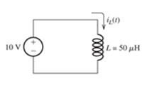
Figure P3 51
The current in the inductance at t = 0 is —100 mA. At what time I, does the current reach +100 mA?
Expert Solution & Answer
Want to see the full answer?
Check out a sample textbook solution
Students have asked these similar questions
The voltage across an inductance L is given by v( t )= V m cos( ωt ). The current is zero at t=0 .Suppose that is very large ideally, approaching infinity. For this voltage, does the inductance approximate either an open or a short circuit? Explain.
The charges of the 2C, C, 2C capacitance capacitors in the figure are qk, qi and qm, respectively. Accordingly, what kind of relationship is there between qk, qi and qm?
Suppose we have a very large capacitance (ideally, infinite) charged to 10 V. What othercircuit element has the same current-voltage relationship? Explain your answer.
Chapter 3 Solutions
Mastering Engineering with Pearson eText -- Standalone Access Card -- for Electrical Engineering: Principles & Applications
Ch. 3 - What is a dielectric material? Give two examples.Ch. 3 - Briefly discuss how current can flow “through” a...Ch. 3 - What current flows through an ideal capacitor if...Ch. 3 - Describe the internal construction of capacitors.Ch. 3 - A voltage of 50 V appears across a 10F capacitor....Ch. 3 - A 2000F capacitor, initially charged to 100V, is...Ch. 3 - A 5F Capacitor ischarged to 1000 V. Determine the...Ch. 3 - The voltage across a 10F capacitor is given by v...Ch. 3 - The voltage across a 1F capacitor is given by...Ch. 3 - Prior to t = 0, a 100F capacitance is uncharged...
Ch. 3 - The current through a 0.5F capacitor is shown in...Ch. 3 - Determine the capacitor voltage, power, and stored...Ch. 3 - A current given by i(t)=Imcos(t) flows through a...Ch. 3 - The current through a 3F capacitor is shown in...Ch. 3 - A constant (dc) current i(t)=3 mA flows into a 50F...Ch. 3 - The energy stored in a 2F capacitor is 200 J and...Ch. 3 - At t=t0 the voltage across a certain capacitance...Ch. 3 - An unusual capacitor has a capacitance that is a...Ch. 3 - For a resistor, what resistance corresponds to a...Ch. 3 - Suppose we have a very large capacitance (ideally,...Ch. 3 - We want to store sufficient energy in a 001-F...Ch. 3 - A 100F capacitor has a voltage given by v(t)=1010...Ch. 3 - How are capacitances combined in series and in...Ch. 3 - Find the equivalent capacitance for each of the...Ch. 3 - Find the equivalent capacitance between terminals...Ch. 3 - A network has a 5F capacitance in series with the...Ch. 3 - What are the minimum and maximum values of...Ch. 3 - Two initially uncharged capacitors C1=15F and...Ch. 3 - Suppose that we are designing a cardiac pacemaker...Ch. 3 - Suppose that we have two 100F capacitors One is...Ch. 3 - Determine the capacitance of a parallel-plate...Ch. 3 - A 100-pF capacitor is constructed of parallel...Ch. 3 - We have a parallel-plate capacitor with plates of...Ch. 3 - Suppose that we have a 1000-pF parallel-plate...Ch. 3 - Two 1F capacitors have an initial voltage of 100 V...Ch. 3 - Prob. 3.36PCh. 3 - Prob. 3.37PCh. 3 - A parallel-plate capacitor is used as a vibration...Ch. 3 - A 0.1F capacitor has a parasitic series resistance...Ch. 3 - Prob. 3.40PCh. 3 - Briefly discuss how inductors are constructed.Ch. 3 - The current flowing through an inductor is...Ch. 3 - If the current through an ideal inductor is...Ch. 3 - Briefly discuss the fluid-flow analogy for an...Ch. 3 - The current flowing through a 2-H inductance is...Ch. 3 - The current flowing through a 100-mH inductance is...Ch. 3 - The current flowing through a 2-H inductance is...Ch. 3 - The voltage across a 2-H inductance is shown in...Ch. 3 - The voltage across a 10 H inductance is given by...Ch. 3 - A 2-H inductance has i(0) = 0 and v(t)=texp(t) for...Ch. 3 - A constant voltage of 10V is applied to a 50H...Ch. 3 - At t = 0, the current flowing in a 05-H inductance...Ch. 3 - The current through a 100-mH inductance is given...Ch. 3 - Prior to t= 0, the current in a 2-H inductance is...Ch. 3 - At t= 0, a constant 5-V voltage source is applied...Ch. 3 - Prob. 3.56PCh. 3 - Al t= 5 s, the energy stored in a 2-H inductor is...Ch. 3 - What value of inductance (having zero initial...Ch. 3 - To what circuit element does a very large...Ch. 3 - The voltage across an inductance L is given by...Ch. 3 - Discuss how inductances are combined in series and...Ch. 3 - Determine the equivalent inductance for each of...Ch. 3 - Find the equivalent inductance for each of the...Ch. 3 - What is the maximum inductance that can be...Ch. 3 - Suppose we want to combine (in series or in...Ch. 3 - Prob. 3.66PCh. 3 - Two inductances L1=1H and L2=2H are connected in...Ch. 3 - A 10-mH inductor has a parasitic series resistance...Ch. 3 - Draw the equivalent circuit for a real inductor,...Ch. 3 - Suppose that the equivalent circuit shown in...Ch. 3 - Consider the circuit shown in Figure P3.71 in...Ch. 3 - The circuit shown in Figure P3.72 has...Ch. 3 - Describe briefly the physical basis for mutual...Ch. 3 - The mutually coupled inductances in Figure P3.74...Ch. 3 - Repeat Problem P3.74 with the dot placed at the...Ch. 3 - a. Derive an expression for the equivalent...Ch. 3 - Consider the parallel inductors shown in Figure...Ch. 3 - Consider the mutually coupled inductors shown in...Ch. 3 - Mutually coupled inductances have...Ch. 3 - The current through a 200-mH inductance is given...Ch. 3 - A 1-H inductance has iL(0)=0 and vL(t)=texp(t) for...Ch. 3 - The current flowing through a 10F capacitor having...Ch. 3 - Determine the equivalent capacitance Ceq for...Ch. 3 - A certain parallel-plate capacitor has plate...Ch. 3 - A 2-mH inductance has iab=0.3sin(2000t)A . Find an...Ch. 3 - Determine the equivalent inductance Leq between...Ch. 3 - Given that vc(t)=10sin(1000t)V , find vs(t)in the...Ch. 3 - Prob. 3.7PTCh. 3 - The current flowing through a 20F capacitor having...
Additional Engineering Textbook Solutions
Find more solutions based on key concepts
Assume a telephone signal travels through a cable at two-thirds the speed of light. How long does it take the s...
Electric Circuits (10th Edition)
Design an ideal inverting op-amp circuit such that the voltage gain is Av=25 . The maximum current in any resis...
Microelectronics: Circuit Analysis and Design
With respect to the circuit in Fig. 5.90, (a) employ Thévenin’s theorem to determine the equivalent network see...
Loose Leaf for Engineering Circuit Analysis Format: Loose-leaf
The current source in the circuit shown generates the current pulse
Find (a) v (0); (b) the instant of time gr...
Electric Circuits. (11th Edition)
Explain the main function of each of the following major components of a PLC: a. Processor module (CPU) b. I/O ...
Programmable Logic Controllers
The voltage source of the circuit shown in Fig. P1.29 is given by s(t)=25cos(4104t45)(V). Obtain an expression ...
Fundamentals of Applied Electromagnetics (7th Edition)
Knowledge Booster


Learn more about
Need a deep-dive on the concept behind this application? Look no further. Learn more about this topic, electrical-engineering and related others by exploring similar questions and additional content below.Similar questions
- A 0.1-μF capacitor has a parasitic series resistance of 10 Ω, as shown in Figure P3.39.Suppose that the voltage across the capacitance is v c ( t )=10 cos( 100t ); find the voltageacross the resistance. In this situation, to find the total voltage v( t )= v r ( t )+ v c ( t ) to within 1percent accuracy, is it necessary to include the parasitic resistance? Repeat if v c ( t )=0.1 cos(10 7 t ).arrow_forwardQ2 b) Illustrate the current waveform for a 100 mH inductor, if the voltage across the inductor is given by Figure Q2(b). c) Calculate the minimum and maximum equivalent inductance that can be given by five 5 mH inductors.arrow_forwardPrior to t=0, the current in a 2-H inductance is zero. Starting at t=0, the current is increased linearly with time to 10 A in 5 s. Then, the current remains constant at 10 A. Sketch the voltage, current, power, and stored energy to scale versus time.arrow_forward
- 5. Discuss why d. It is necessary to use the geometric means radius in the formula for the inductance calculation whereas the formula for the capacitance calculation uses the actual radius.arrow_forwardCapacitance= 4uF2) Determine the time constant of the circuit for the capacities 3) For the capacity value, calculate the estimated time to come to the final state.4) Plot capacitor current and voltage graphs and show if it works in harmony with the time constant you calculated. NOTE: if you want you can use falstad online circuit simulator.arrow_forwardSuppose that a parallel-plate capacitor has a dielectric that breaks down if the electric field exceeds K V/m. Thus, the maximum voltage rating of the capacitor is V max =K d, where d is the separation between the plates. In working Problem P3.33, we find that the maximum energy that can be stored is w max = 1 2 ∈ r ∈ 0 K 2 (Vol) in which Vol is the volume of the dielectric. Given that K=32× 10 5 V/m and that ∈ r =1 (the approximate values for air), find the dimensions of a parallel-plate capacitor having square plates if it is desired to store 1 mJ at a voltage of 1000 V in the least possible volume.arrow_forward
- P5 Determine the current in each mesh of the circuit shown in Figure 3. if the switch is closed in the instant t = 0 en which the charge of the capacitor is 0.arrow_forwardThe figure shows an electrical circuit with an ideal source ε1 = 12 [V], a real source ε2 = 9 [V] and r1 = 1 [Ω], eight resistors and two capacitors. Switches A and B areThey are originally open and the charge on the capacitors is zero. If at t = 0 [s] switch A opens and switch B closes, determine:d) The potential difference of resistor R8 at t = 2.6 [s].e) The time required for the potential difference of the equivalent capacitor to reach the maximum possible value. Justify your answer.arrow_forwardReflect and elaborate comprehensively the concept, application and importance of these topic. CAPACITANCE AND DIELECTRICSarrow_forward
- Having stabilized the fuel, you look to your computer for next steps. You are told that the spacecraft uses a "start capacitor" that must reach a required voltage in order to start its engine. This voltage is determined by the fixed capacitance and charge as a function of time, q(t) . These capacitors are charged and stored in your current location and must be brought to the spacecraft. Your computer provides you with the following definitions: Charge: The charge as a function of time is q(t)=∫i(t)dt , where i(t)=36t^5+15t^2−6 is the current as a function of time. You need to provide the computer with the function q(t) in order for it to appropriately charge the start capacitor. If an unknown constant is needed, it can be included using "+ C", being sure to use a capital letter as the lowercase is used for capacitance. q(t)=arrow_forwardA constant voltage of 10 V is applied to a 50-μH inductance, as shown in Figure P3.51. The current in the inductance at t=0 is -100 mA. At what t x time does the current reach +100 mA?arrow_forwardTwo initially uncharged capacitors C 1 = 15 μF and C 2 =10 μF are connected in series. Then, a 10-V source is connected to the series combination, as shown in Figure P3.28. Find the voltages v1 and v2 after the source is applied. [Hint: The charges stored on the two capacitors must be equal, because the current is the same for both capacitors.]arrow_forward
arrow_back_ios
SEE MORE QUESTIONS
arrow_forward_ios
Recommended textbooks for you
 Introductory Circuit Analysis (13th Edition)Electrical EngineeringISBN:9780133923605Author:Robert L. BoylestadPublisher:PEARSON
 Delmar's Standard Textbook Of ElectricityElectrical EngineeringISBN:9781337900348Author:Stephen L. HermanPublisher:Cengage Learning
 Programmable Logic ControllersElectrical EngineeringISBN:9780073373843Author:Frank D. PetruzellaPublisher:McGraw-Hill Education
 Fundamentals of Electric CircuitsElectrical EngineeringISBN:9780078028229Author:Charles K Alexander, Matthew SadikuPublisher:McGraw-Hill Education
 Electric Circuits. (11th Edition)Electrical EngineeringISBN:9780134746968Author:James W. Nilsson, Susan RiedelPublisher:PEARSON
 Engineering ElectromagneticsElectrical EngineeringISBN:9780078028151Author:Hayt, William H. (william Hart), Jr, BUCK, John A.Publisher:Mcgraw-hill Education,
Introductory Circuit Analysis (13th Edition)
Electrical Engineering
ISBN:9780133923605
Author:Robert L. Boylestad
Publisher:PEARSON
Delmar's Standard Textbook Of Electricity
Electrical Engineering
ISBN:9781337900348
Author:Stephen L. Herman
Publisher:Cengage Learning
Programmable Logic Controllers
Electrical Engineering
ISBN:9780073373843
Author:Frank D. Petruzella
Publisher:McGraw-Hill Education
Fundamentals of Electric Circuits
Electrical Engineering
ISBN:9780078028229
Author:Charles K Alexander, Matthew Sadiku
Publisher:McGraw-Hill Education
Electric Circuits. (11th Edition)
Electrical Engineering
ISBN:9780134746968
Author:James W. Nilsson, Susan Riedel
Publisher:PEARSON
Engineering Electromagnetics
Electrical Engineering
ISBN:9780078028151
Author:Hayt, William H. (william Hart), Jr, BUCK, John A.
Publisher:Mcgraw-hill Education,
Inductors Explained - The basics how inductors work working principle; Author: The Engineering Mindset;https://www.youtube.com/watch?v=KSylo01n5FY;License: Standard Youtube License