
DESIGN OF MACHINERY (LL) >C<
6th Edition
ISBN: 9781264001330
Author: Norton
Publisher: MCGRAW-HILL LEARNING SOLN.(CC)
expand_more
expand_more
format_list_bulleted
Videos
Textbook Question
Chapter 3, Problem 3.36P
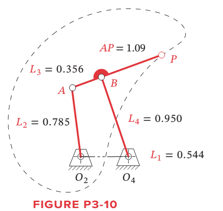
Find the Grashof condition, inversion, any limit positions, and the extreme values of the transmission angle (to graphical accuracy) of the linkage in Figure P3-10.
Expert Solution & Answer
Want to see the full answer?
Check out a sample textbook solution
Students have asked these similar questions
The linkage in Figure P7-5b has 04A = O2A = 0.75 , AB = 1.5 , and AC = 1.2 in . The effective crank angle in the position shown is 77º and angle BAC = 30 ° . Find a3 , AA , AB , Ac for the position shown for m2 = 15 rad / sec and a2 = 10 rad / sec2 in the directions shown using an analytical method . ( Hint : Create an effective linkage for the position shown and analyze it as a pin - jointed fourbar . ) the linkage has a parallelogram form Assume rolling contact C 02 A 3 . B 02 02 T
Problem 2
The linkage in Figure P7-5b has O,A = O2A = 0.75, AB= 1.5, and AC = 1.2
in. The effective crank angle in the position shown is 77° and angle BAC =
30°. Find a3, A4, AB,Ac for the position shown for @2 = 15 rad/sec and a2 =
10 rad/sec in the directions shown using an analytical method.
(Hint: Create an effective linkage for the position shown and analyze it as a
pin-jointed fourbar.)the linkage has a parallelogram form
Assume rolling contact
C
@2
A
3
В
a2
2
4
04
Figure below shows a four-bar linkage (non-scaled diagram) at an instant. The input
angle is equal to the output angle (02 - 04) and the transmission angle is 30°. The
input link is extended beyond joint B and an input force (Fin) is applied at the end of
it, while an output force is drawn from the midpoint of the output link. If an output
force of 30 N is desired from an input force of 10 N, how far the input link should be
extended, i.e., what is the distance from point B to the point where Fin is applied.
Fin
B
out
undefined
02
04
A.
Non-scaled diagram; AB = 10, CD=r4 = 30 (output), all in mm
Chapter 3 Solutions
DESIGN OF MACHINERY (LL) >C<
Ch. 3 - Define the following examples as path, motion, or...Ch. 3 - Design a fourbar Grashof crank-rocker for 90 of...Ch. 3 - Prob. 3.3PCh. 3 - Design a fourbar mechanism to give the two...Ch. 3 - Prob. 3.5PCh. 3 - Prob. 3.6PCh. 3 - Repeat Problem 3-2 with a quick-return time ratio...Ch. 3 - Design a sixbar drag link quick-return linkage for...Ch. 3 - Design a crank-shaper quick-return mechanism for a...Ch. 3 - Find the two cognates of the linkage in Figure...
Ch. 3 - Find the three equivalent geared fivebar linkages...Ch. 3 - Design a sixbar single-dwell linkage for a dwell...Ch. 3 - Design a sixbar double-dwell linkage for a dwell...Ch. 3 - Figure P3-3 shows a treadle-operated grinding...Ch. 3 - Figure P3-4 shows a non-Grashof fourbar linkage...Ch. 3 - Prob. 3.16PCh. 3 - Prob. 3.17PCh. 3 - Prob. 3.18PCh. 3 - Design a pin-jointed linkage that will guide the...Ch. 3 - Figure P3-6 shows a V-link off-loading mechanism...Ch. 3 - Prob. 3.21PCh. 3 - Prob. 3.22PCh. 3 - Figure P3-8 shows a fourbar linkage used in a...Ch. 3 - Prob. 3.24PCh. 3 - Prob. 3.25PCh. 3 - Prob. 3.26PCh. 3 - Prob. 3.27PCh. 3 - Prob. 3.28PCh. 3 - Prob. 3.29PCh. 3 - Prob. 3.30PCh. 3 - Design a Hoeken straight-line linkage to give...Ch. 3 - Design a Hoeken straight-line linkage to give...Ch. 3 - Prob. 3.33PCh. 3 - Prob. 3.34PCh. 3 - Prob. 3.35PCh. 3 - Find the Grashof condition, inversion, any limit...Ch. 3 - Prob. 3.37PCh. 3 - Prob. 3.38PCh. 3 - Prob. 3.39PCh. 3 - Draw the Roberts diagram and find the cognates of...Ch. 3 - Prob. 3.41PCh. 3 - Find the Grashof condition, any limit positions,...Ch. 3 - Prob. 3.43PCh. 3 - Prob. 3.44PCh. 3 - Prob. 3.45PCh. 3 - Prob. 3.46PCh. 3 - Prob. 3.47PCh. 3 - Prob. 3.48PCh. 3 - Prob. 3.49PCh. 3 - Prob. 3.50PCh. 3 - Prob. 3.51PCh. 3 - Prob. 3.52PCh. 3 - Prob. 3.53PCh. 3 - Prob. 3.54PCh. 3 - Prob. 3.55PCh. 3 - Prob. 3.56PCh. 3 - Prob. 3.57PCh. 3 - Prob. 3.58PCh. 3 - Prob. 3.59PCh. 3 - Prob. 3.60PCh. 3 - Prob. 3.61PCh. 3 - Prob. 3.62PCh. 3 - Prob. 3.63PCh. 3 - Prob. 3.64PCh. 3 - Prob. 3.65PCh. 3 - Prob. 3.66PCh. 3 - Design a fourbar Grashof crank-rocker for 120 of...Ch. 3 - Prob. 3.68PCh. 3 - Design a fourbar Grashof crank-rocker for 80 of...Ch. 3 - Design a sixbar drag link quick-return linkage for...Ch. 3 - Design a crank shaper quick-return mechanism for a...Ch. 3 - Design a sixbar, single-dwell linkage for a dwell...Ch. 3 - Design a sixbar, single-dwell linkage for a dwell...Ch. 3 - Prob. 3.74PCh. 3 - Using the method of Example 3-11, show that the...Ch. 3 - Prob. 3.76PCh. 3 - Prob. 3.77PCh. 3 - Prob. 3.78PCh. 3 - The first set of 10 coupler curves on page 1 of...Ch. 3 - Prob. 3.80PCh. 3 - Prob. 3.81PCh. 3 - Prob. 3.82PCh. 3 - Prob. 3.83PCh. 3 - Prob. 3.84PCh. 3 - Prob. 3.85PCh. 3 - Prob. 3.86PCh. 3 - Prob. 3.87PCh. 3 - The side view of the upper section of a...Ch. 3 - Design a fourbar mechanism to give the three...Ch. 3 - Design a fourbar mechanism to give the three...Ch. 3 - Design a fourbar Grashof crank-rocker for 60...Ch. 3 - Design a crank-shaper quick-return mechanism for a...Ch. 3 - Figure P3-22 shows a non-Grashof fourbar linkage...Ch. 3 - Prob. 3.94PCh. 3 - Design a fourbar Grashof crank-rocker for 80...Ch. 3 - Design a sixbar drag link quick-return linkage for...
Knowledge Booster


Learn more about
Need a deep-dive on the concept behind this application? Look no further. Learn more about this topic, mechanical-engineering and related others by exploring similar questions and additional content below.Similar questions
- The link lengths and the value of 2 and offset for some fourbar crank-slide linkages are defined in Table 1. The linkage configuration and terminology are shown in Figure 1. For the rows assigned, find (a) all possible solutions for angle and slider position d by vector loop method. (b) the transmission angle corresponding to angle 83. (Hint: Treat the vector R4 as virtual rocker) Show your work in details: vector loop, vector equations, solution procedure. Table 1 Row a b с offset 02 Link 2 1.4 3 5 A R2 0₂ Link 3 4 8 20 slider axis. R3 Link 3 R₂ d R₁ Figure 1. 0₁ Offset 1 2 -5 С B R4 T 84 X Q2 45° -30° 225°arrow_forwardProblem 4-6a The link lengths (a, b, c, d) and the value of 2 for a crank-rocker linkage are defined as 2, 7, 9, 6, 30°, respectively. Draw the scaled linkage. Find all possible solutions (both open and crossed) for angles 03 and 04 graphically. Орen B A LNCS 4 a GCS र 4 4" Crossed (This is not the scaled kinematic diagram.) Problem 4-7a Repeat Problem 4-6a except solve by the vector loop method.arrow_forwarddo fast.arrow_forward
- 1. Find a combination of link lengths where motion of a point on output link is one quarter of a circle. 2. Find the value of all 0, 0, 0, and y in open and close configuration Read the value of link lengths and the input angle 8., then use the formulae given below to calculate the value of unknowns 03, 0, and y K₁ = = K₂= d K2 K3 = a²-b²+c²+d² 2ac A = cos 0₂ - K₁ - K₂ cos 0₂ + K3 B = -2 sin 0₂ C = K₁ (K₂ + 1) cos 02 + K3 -B± √B²-4AC 2A 0412 = 2tan-1 d K₁ = — K5 = c²d²a²-6² 2ab D = cos 0₂ - K₁ - K4 cos 0₂ + K5 E = -2 sin 0₂ FK₁+ (K₁ - 1) cos 02 +K5 0312 2 tan-1 (-E± -E± √E²4DF 2D Y = 04-03arrow_forward4arrow_forwardThe figure below shows an offset slider crank linkage. The links lengths are: link2 = a= 100 mm and link3 = b = 600 mm. The offset is c = 190 mm. we need to : 1. determine the maximum horizontal position of the slider B (dmax) and the corresponding input angle 02 2. determine the minimum horizontal position of the slider B (dmin) and the corresponding input angle 02 Y 03 y В R3 R4 R, 04 R2 02 d ► X R1 The maximum horizontal position of the slider is dmax = Choose... + The input angle 02 corresponding to dmax , in degree and measured CCW from X axis, is = Choose... + The minimum horizontal position of the slider is dmin = Choose... + The input angle 02 corresponding to dmin , in degree and measured CcW from X axis, is = Choose.. +arrow_forward
- Problem 2 The linkage in Figure P7-5b has o4A = o2A = 0.75, AB = 1.5, and AC = 1.2 in. The effective crank angle in the position shown is 77° and angle BAC = 30°. Find a3, AA, AB, Ac for the position shown for w2 = 15 rad/sec and a2 = 10 rad/sec^2 in the directions shown using an analytic method. (Hint: Create an effective linkage for the position shown and analyze it as a pin-jointed fourbar.) the linkage has a parallelogram form Assume rolling contactarrow_forwardProblem 2 The linkage in Figure P7-5b has O4A = O2A = 0.75, AB = 1.5, and AC = 1.2 in. The effective crank angle in the position shown is 77° and angle BAC = 30°. Find a3, AA. AB,Ac for the position shown for w2 = 15 rad/sec and a2 = 10 rad/sec^2 in the directions shown using an analytic method. (Hint: Create an effective linkage for the position shown and analyze it as a pin-jointed fourbar.)the linkage has a parallelogram form Assume rolling contactarrow_forwardAll pertinent rigid dimensions are specified for the linkage shown. Note that the ground pivot for the input link is at the origin of the coordinate system. The input angle []in is currently 170° measured from the x axis as shown. The figure is not exactly to scale, but it is reasonably close for checking purposes. (a) Calculate the value of the angle []out as shown on the figure. Use the equations developed from the loop closure method. Note that you will need to incorporate a change of coordinate axes orientation to the axes defined for the loop closure equations. (b) Calculate the absolute location of point P with respect to the coordinate axes shown. 18 30° 9° 9 P 20 50° -170° Xarrow_forward
- Please help me with this Kinematics problem. This is for kinematics & dynamics of machines. Thank you.arrow_forwardFigure P6-29 shows a drum pedal mechanism. O2A = 100 mm at 162° and rotates to 171° at A°. 0204 = 56 mm, AB = 28 mm, AP = 124 mm, and 04B = 64 mm. The distance from 04 to Fin is 48 mm. Find and plot the mechanical advantage and the velocity ratio of the linkage over its range of motion. If the input velocity Vin is a constant magnitude of 3 m/ see, and Fin is constant at 50 N, find the output velocity and output force over the range of motion and the power in.arrow_forwardStrictly use graphical method and Find T2. Do not copy from chegg their all answers are wrong.If you do I'll give thumbs down.arrow_forward
arrow_back_ios
SEE MORE QUESTIONS
arrow_forward_ios
Recommended textbooks for you
 Elements Of ElectromagneticsMechanical EngineeringISBN:9780190698614Author:Sadiku, Matthew N. O.Publisher:Oxford University Press
 Mechanics of Materials (10th Edition)Mechanical EngineeringISBN:9780134319650Author:Russell C. HibbelerPublisher:PEARSON
 Thermodynamics: An Engineering ApproachMechanical EngineeringISBN:9781259822674Author:Yunus A. Cengel Dr., Michael A. BolesPublisher:McGraw-Hill Education
 Control Systems EngineeringMechanical EngineeringISBN:9781118170519Author:Norman S. NisePublisher:WILEY
 Mechanics of Materials (MindTap Course List)Mechanical EngineeringISBN:9781337093347Author:Barry J. Goodno, James M. GerePublisher:Cengage Learning
 Engineering Mechanics: StaticsMechanical EngineeringISBN:9781118807330Author:James L. Meriam, L. G. Kraige, J. N. BoltonPublisher:WILEY
Elements Of Electromagnetics
Mechanical Engineering
ISBN:9780190698614
Author:Sadiku, Matthew N. O.
Publisher:Oxford University Press
Mechanics of Materials (10th Edition)
Mechanical Engineering
ISBN:9780134319650
Author:Russell C. Hibbeler
Publisher:PEARSON
Thermodynamics: An Engineering Approach
Mechanical Engineering
ISBN:9781259822674
Author:Yunus A. Cengel Dr., Michael A. Boles
Publisher:McGraw-Hill Education
Control Systems Engineering
Mechanical Engineering
ISBN:9781118170519
Author:Norman S. Nise
Publisher:WILEY
Mechanics of Materials (MindTap Course List)
Mechanical Engineering
ISBN:9781337093347
Author:Barry J. Goodno, James M. Gere
Publisher:Cengage Learning
Engineering Mechanics: Statics
Mechanical Engineering
ISBN:9781118807330
Author:James L. Meriam, L. G. Kraige, J. N. Bolton
Publisher:WILEY
Polymer Basics; Author: Tonya Coffey;https://www.youtube.com/watch?v=c5gFHpWvDXk;License: Standard youtube license