
Concept explainers
Videos
A
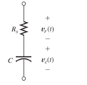
Figure P3.39
Want to see the full answer?
Check out a sample textbook solution
Chapter 3 Solutions
Electrical Engineering: Principles & Applications Plus Mastering Engineering with Pearson eText -- Access Card Package (7th Edition)


- Two initially uncharged capacitors C 1 = 15 μF and C 2 =10 μF are connected in series. Then, a 10-V source is connected to the series combination, as shown in Figure P3.28. Find the voltages v1 and v2 after the source is applied. [Hint: The charges stored on the two capacitors must be equal, because the current is the same for both capacitors.]arrow_forwardSuppose that a parallel-plate capacitor has a dielectric that breaks down if the electric field exceeds K V/m. Thus, the maximum voltage rating of the capacitor is V max =K d, where d is the separation between the plates. In working Problem P3.33, we find that the maximum energy that can be stored is w max = 1 2 ∈ r ∈ 0 K 2 (Vol) in which Vol is the volume of the dielectric. Given that K=32× 10 5 V/m and that ∈ r =1 (the approximate values for air), find the dimensions of a parallel-plate capacitor having square plates if it is desired to store 1 mJ at a voltage of 1000 V in the least possible volume.arrow_forwardWhat is the practical application of a circuit that you can tune such that it reaches some minimum resistance? Would there be an application to being able to tune where that minimum occurs, by changing the capacitance or inductance of the circuit?arrow_forward
- A 150-volt electromotive force is applied to an RC-series circuit in which the resistance is 1500 ohm and the capacitance is 5 micro Farad (uF). If q(0)=0, find the charge and current at t=0.005 s. charge: q = micro Farad (uF) current: i = milli ampere (mA) Determine the charge as t approaches infinity. charge: q= micro Farad (uF)arrow_forwardA potential difference of V = 58.0 V is applied across a circuit with capacitances C1 = 4.7 nF, C2 = 3.1 nF, and C3= 1.3 nF, as shown in the figure.a) What is the magnitude and sign of q3l, the charge on the left plate of C3 (marked by point A)? b) What is the electric potential difference, V3, across C3? c) What is the magnitude and sign of the charge q2r, on the right plate of C2 (marked by point B)?arrow_forwardThe current through a 3-μF capacitor is shown in Figure P3.14. At t = 0, the voltage is v(0) = 10 V. Sketch the voltage, power, and stored energy to scale versus time.arrow_forward
- A series RC circuit is not switched on and the initial state charge of capacitance ?CO = 10 V. In the circuit voltage source E = 50 V DC. Resistance R = 44 Ω and capacitance C = 100 μF. Give the answers to two decimal places. a) Give time constant Tau of circuit (ms) b) Calculate current after the switch k is closed at the moment t = 0.2 ms. (A) c) Calculate current after the switch k is closed at the moment t = 2*Tau. (A)arrow_forwardFor the capacitor network shown in Figure(Q2a) above (which has reachedsteady state i.e. on for a very long time), calculate:i. The total capacitance, CT , for the entire networkii. The voltage across capacitor C2iii. The total charge stored across capacitor C2iv. The energy stored in capacitor C2arrow_forwardThe circuit shown in Figure-2 is at steady state before the switch closes at time t = 0. The input to the circuit is the voltage of the voltage source, 12 V. The output of this circuit is the voltage across the capacitor, v(t). -Use Matlab Simscape Electrical to build and plot the output, v(t), as a function of t (by using scope). Use the plot to obtain an analytic representation of v(t) for t > 0. Hint: We expect v(t) = A + Be–t/τ for t > 0, where A, B, and τ are constants to be determined. Modify the circuit given in this example (build figure-2) https://www.mathworks.com/help/physmod/simscape/ug/operating-point-rlc-transient-response.html You will obtain a graph as figure 2-b and by using graph and substituting three ‘t’ values to v(t) then you can find A, B and τ.arrow_forward
- the emf source, E=3.2 V, of the circuit shown in the figure has negligible internal resistance. the resistors have resistances R1=3 ohm and R2=4.2 ohm. the capacitor has a capacitance C= 3.1uF. A) determine the time constant t , in units of microseconds for charging the capacitor. B) what is the charge Q on the capacitor in units of microcoulomb?arrow_forwardA resistance of 100 Ω, an inductance of 0.1 H, and a capacitance of 5(10−5) F are connected in series.If the total electromotive force is given by 110 sin 377t, such that at t = 0,Q = 0, and i = 0, find thecurrent for t > 0.arrow_forwardFor the circuit shown in the figure, in which the capacitor is initially fully discharged. If the source voltage V is 17 Volts, the capacitance of capacitor C is 24 mF; and the values of the resistors in Ω are: R1 = 2250 , R2 = 1071 , R3 = 2455 , R4 = 1199 and R5 = 1043 Determine the voltage across the capacitor in Volts after 15 minutes have elapsed since the circuit is energized. ..arrow_forward
 Introductory Circuit Analysis (13th Edition)Electrical EngineeringISBN:9780133923605Author:Robert L. BoylestadPublisher:PEARSON
 Delmar's Standard Textbook Of ElectricityElectrical EngineeringISBN:9781337900348Author:Stephen L. HermanPublisher:Cengage Learning
 Programmable Logic ControllersElectrical EngineeringISBN:9780073373843Author:Frank D. PetruzellaPublisher:McGraw-Hill Education
 Fundamentals of Electric CircuitsElectrical EngineeringISBN:9780078028229Author:Charles K Alexander, Matthew SadikuPublisher:McGraw-Hill Education
 Electric Circuits. (11th Edition)Electrical EngineeringISBN:9780134746968Author:James W. Nilsson, Susan RiedelPublisher:PEARSON
 Engineering ElectromagneticsElectrical EngineeringISBN:9780078028151Author:Hayt, William H. (william Hart), Jr, BUCK, John A.Publisher:Mcgraw-hill Education,