
Videos
Two inductances
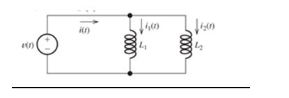
Figure P3.67

Trending nowThis is a popular solution!

Chapter 3 Solutions
Electrical Engineering: Principles & Applications Plus Mastering Engineering with Pearson eText -- Access Card Package (7th Edition)


- A potential difference of V = 58.0 V is applied across a circuit with capacitances C1 = 4.7 nF, C2 = 3.1 nF, and C3= 1.3 nF, as shown in the figure.a) What is the magnitude and sign of q3l, the charge on the left plate of C3 (marked by point A)? b) What is the electric potential difference, V3, across C3? c) What is the magnitude and sign of the charge q2r, on the right plate of C2 (marked by point B)?arrow_forwardThe circuit shown in Figure-2 is at steady state before the switch closes at time t = 0. The input to the circuit is the voltage of the voltage source, 12 V. The output of this circuit is the voltage across the capacitor, v(t). -Use Matlab Simscape Electrical to build and plot the output, v(t), as a function of t (by using scope). Use the plot to obtain an analytic representation of v(t) for t > 0. Hint: We expect v(t) = A + Be–t/τ for t > 0, where A, B, and τ are constants to be determined. Modify the circuit given in this example (build figure-2) https://www.mathworks.com/help/physmod/simscape/ug/operating-point-rlc-transient-response.html You will obtain a graph as figure 2-b and by using graph and substituting three ‘t’ values to v(t) then you can find A, B and τ.arrow_forwardQ2. For the RL circuit, shown in figure (1), the switch has been in position “a” for a long time, before switching to position “b”, at t = 0. Find a) a time-expression for the current through the inductor, i(t), for t > 0, b) the values of v(0- ), v(0+ ), and v(∞), and c) the powers dissipated in the 3-Ω resistor, at t = 3 ms.arrow_forward
- In the Figure Q3(c), determine the value of R for which the steady-state energy storedin the inductor will be 0.25J.arrow_forwardFor the solution provided, i do not understand, when finding w = infinity, why do we take into account the imaginary numbers only (R2 /(R1+R2))? Pls provide the derivation of the formula as shown in the solutionarrow_forwardFor the capacitor network shown in Figure(Q2a) above (which has reachedsteady state i.e. on for a very long time), calculate:i. The total capacitance, CT , for the entire networkii. The voltage across capacitor C2iii. The total charge stored across capacitor C2iv. The energy stored in capacitor C2arrow_forward
- A 150-volt electromotive force is applied to an RC-series circuit in which the resistance is 1500 ohm and the capacitance is 5 micro Farad (uF). If q(0)=0, find the charge and current at t=0.005 s. charge: q = micro Farad (uF) current: i = milli ampere (mA) Determine the charge as t approaches infinity. charge: q= micro Farad (uF)arrow_forwardSuppose that a parallel-plate capacitor has a dielectric that breaks down if the electric field exceeds K V/m. Thus, the maximum voltage rating of the capacitor is V max =K d, where d is the separation between the plates. In working Problem P3.33, we find that the maximum energy that can be stored is w max = 1 2 ∈ r ∈ 0 K 2 (Vol) in which Vol is the volume of the dielectric. Given that K=32× 10 5 V/m and that ∈ r =1 (the approximate values for air), find the dimensions of a parallel-plate capacitor having square plates if it is desired to store 1 mJ at a voltage of 1000 V in the least possible volume.arrow_forwardIn the circuit shown in the figure, the inductor has inductance ?=3.50 HL=3.50 H and negligible internal resistance. The battery has a voltage of ?b=16.0 VVb=16.0 V and is connected in series to a resistor of resistance ?1=14.0 Ω.R1=14.0 Ω. A second resistor has a resistance of ?2=145 Ω.R2=145 Ω. The switch ?S has been open for a long time. At time ?=0,t=0, the switch is closed. What is the current ?b,0Ib,0 through the battery, the current ?2,0I2,0 through resistor ?2,R2, and the current ?L,0IL,0 through the inductor at ?=0.t=0. What is the current ?b,∞Ib,∞ through the battery, the current ?2,∞I2,∞ through resistor ?2,R2, and the current ?L,∞IL,∞ through the inductor long after the switch is closed (i.e., ?=∞).arrow_forward
- The figure shows an electrical circuit with an ideal source ε1 = 12 [V], a real source ε2 = 9 [V] and r1 = 1 [Ω], eight resistors and two capacitors. Switches A and B areThey are originally open and the charge on the capacitors is zero. If at t = 0 [s] switch A opens and switch B closes, determine:d) The potential difference of resistor R8 at t = 2.6 [s].e) The time required for the potential difference of the equivalent capacitor to reach the maximum possible value. Justify your answer.arrow_forwardConsider the circuit shown in Figure P3.71, in which v C ( t )=10 sin( 1000t ) V, with the argument of the sine function in radians. Find i(t), vL(t), v(t), the energy stored in the capacitance, the energy stored in the inductance, and the total stored energy. Show that the total stored energy is constant with time. Comment on the results.arrow_forwardQuestion 6 Given a formula for i(t)=10sin(200pit+pi/8) across a capacitor (C=5microfarads). Find the expression of the voltage v(t) across the capcitor. Where Im confused is after integrating the Current and dividing it by C=5microfarads do we need to add +K at the end of the expression? Full explainthe this question very fast solution sent me step by step Don't ignore any part all part work u Text typing work only not allow paper work ......arrow_forward
 Introductory Circuit Analysis (13th Edition)Electrical EngineeringISBN:9780133923605Author:Robert L. BoylestadPublisher:PEARSON
 Delmar's Standard Textbook Of ElectricityElectrical EngineeringISBN:9781337900348Author:Stephen L. HermanPublisher:Cengage Learning
 Programmable Logic ControllersElectrical EngineeringISBN:9780073373843Author:Frank D. PetruzellaPublisher:McGraw-Hill Education
 Fundamentals of Electric CircuitsElectrical EngineeringISBN:9780078028229Author:Charles K Alexander, Matthew SadikuPublisher:McGraw-Hill Education
 Electric Circuits. (11th Edition)Electrical EngineeringISBN:9780134746968Author:James W. Nilsson, Susan RiedelPublisher:PEARSON
 Engineering ElectromagneticsElectrical EngineeringISBN:9780078028151Author:Hayt, William H. (william Hart), Jr, BUCK, John A.Publisher:Mcgraw-hill Education,