Concept explainers
Videos
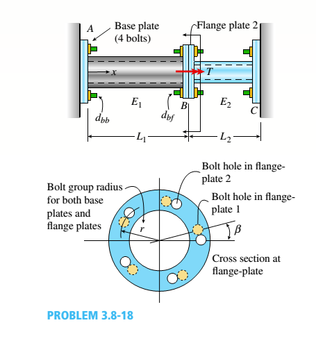
Two pipes {L, = 2.5 m and L, = 1.5 m) are joined al B by flange plales (thickness (, = 14 mm) with five bolts [dlt, = 13 mm] arranged in a circular pal tor n (see figure). Also, each pipe segment is atlaehed to a wall (at .1 and ( '. see figure! using a base plate Uh = 15 mm) and four bolts (dM, = 16 mm). All bolts are tightened until just snug. Assume £, = 110 GPa,E2 = 73 GPa,», = 0.33,andv, = 0.25. Neglect the self-weight of the pipes, and assume the pipes are in a stress-free stale initially. The cross-sectional areas of the pipes are At = 1500 mm: and A2 = (3/5)4. The ollter diameter of Pipe 1 is 60 mm. The outer diameter of Pipe 2 is equal to the inner diameter of Pipe 1. The bolt radius r = 64 mm for both base and flange plates.
(a)
If torque '/'is applied at .v = Lt. find an expression for reactive torques Iit and IL in terms of T.
(b)
Find the maximum load variable /'(i.e., Tmal) if allowable torsional stress in the two pipes is
Tall0* = 65 MPa-id Draw torsional moment iTMD i and torsional displacement (TDD) diagrams. Label all key ordinales. What is '/>.ll('.'
(d) Find mail, if allowable shear and bearing stresses in the base plate and flange bolts cannot be exceeded. Assume allowable stresses in shear an.: :vari:'.g I all bolls are r |Nill, = 45 MPa andtr MaK =90 MPa.
(e) Remove torque Tat x — L,. Now assume the flange-plate bolt holes are misaligned by some angle ß (see figure). Find the expressions for reactive torques Rx and R2 if the pipes are twisted to align the flange-plate bolt holes, bolts are then inserted, and the pipes released.
(f) What is the maximum permissible misalignment angle ß mix if allowable stresses in shear and bearing for all bolts [from part (d)] are not to be exceeded?
(a)
The reactive torque in terms of torque.
Answer to Problem 3.8.18P
The reactive torque at point (A) is =
The reactive torque at point (B) is =
Explanation of Solution
Given information:
Figure (1) shows the systematic diagram of the system:
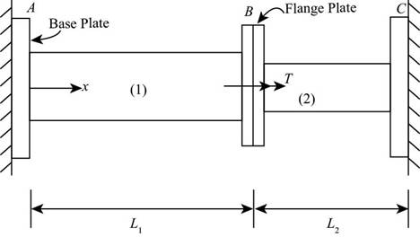
Figure-(1)
The length of first pipe is
Write the expression for cross sectional area of the pipe (1).
Here, the cross sectional area of the pipe (1) is
Write the expression for cross sectional area of the pipe (2).
Here, the cross sectional area of the pipe (2) is
Write the expression for the thickness of the pipe (1).
Here, the thickness of the pipe (1) is
Write the expression for the thickness of the pipe (2).
Here, the thickness of the pipe (2) is
Write the expression for polar moment of inertia for pipe (1).
Here, the polar moment of inertia of pipe (1) is
Write the expression for polar moment of inertia for pipe (2).
Here, the polar moment of inertia of pipe (2) is
Write the expression for modulus of rigidity for pipe (1).
Here, modulus of rigidity for pipe (1) is
Write the expression for modulus of rigidity for pipe (2).
Here, modulus of rigidity for pipe (2) is
Figure-(2) shows free body diagram of the system with internal torque and reactions at the end:
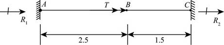
Figure-(2)
Write the expression of equilibrium condition for figure (2)
Here, the reaction torque acting at the point (A) is
Write the expression for torsional flexibility of pipe (1)
Here, the torsional rigidity of pipe (1) is
Write the expression for torsional flexibility of pipe (2)
Here, the torsional rigidity of pipe (1) is
Write the expression for angle of twist for pipe (1)
Here, the angle of twist for pipe (1) is
Write the expression for angle of twist for pipe (2)
Here, the angle of twist for pipe (1) is
Since, the angle of twist in pipe (1) and pipe (2) are opposite in direction
Substitute,
Calculation:
Substitute
Substitute
Substitute
Substitute
Substitute
Substitute
Substitute
Substitute
Substitute
Substitute
Substitute
Substitute
Conclusion:
The reactive torque at point (A) is
The reactive torque at point (B) is
(b)
The maximum load variable
Answer to Problem 3.8.18P
The maximum load variable
Explanation of Solution
Given information:
Permissible torsional stress in two pipes is
Write the expression for maximum load in pipe (1).
Here, maximum load in the pipe (1) is
Write the expression for maximum load in pipe (1).
Here, maximum load in the pipe (2) is
Write the expression for maximum load variable in pipe (1).
Here, the maximum load variable is
Calculation:
Substitute
Substitute
Since, the pipe (1) is greater, the maximum load variable in pipe (1).
Substitute
Conclusion:
The maximum load variable is =
(c)
The torsional moment diagrams.
The torsional displacement diagrams.
The maximum angle of twist.
Answer to Problem 3.8.18P
The maximum angle of twist is
Explanation of Solution
Given information:
Figure (3) shows torsional moment diagram and torsional displacement diagram for the given system.
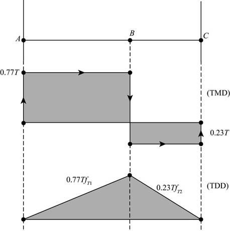
Figure-(3)
Write the expression for maximum angle of twist
Here, maximum angle of twist is =
Calculation:
Substitute
Conclusion:
The maximum angle of twist is =
(c)
The maximum torque for limiting value shear and bearing stress of base plate and flange bolts.
Answer to Problem 3.8.18P
The maximum torque for limiting value shear and bearing stress of base plate and flange bolts is =
Explanation of Solution
Given information:
The permissible shear stress for all bolts is
Write the expression for cross -sectional area of the base plate bolt.
Here, the cross-sectional area of the base plate bolt is
Write the expression for cross sectional area of the flange plate bolt.
Here, the cross-sectional area of the flange plate bolt is
Write the expression for maximum shear load in base plate bolt.
Here, the maximum shear load in base plate is
Here, the maximum shear load in flange plate is
Write the expression for area of the base plate bolt.
Here, the area of base plate bolt is
Write the expression for area of the flange plate bolt.
Here, the area of base plate bolt is
Write the expression for bearing load on base plate
Here, the maximum shear load in base plate is
Here, the maximum shear load in flange plate is
Calculation:
Substitute
Substitute
Substitute
Substitute
Substitute
Substitute
Substitute
Substitute
Conclusion:
The maximum torque for limiting value shear and bearing stress of base plate and flange bolts is =
Want to see more full solutions like this?
Chapter 3 Solutions
Mechanics of Materials - Text Only (Looseleaf)


- A rigid Trame ABC is formed by welding two steel pipes at B (see figure). Each pipe has cross-sectional area A = 11.31 × 10 mm2, moment of inertia I = 46.37 × 106 mm4, and outside diameter d = 200 mm. Find the maximum tensile and compressive stresses e1and e2, respectively, in the frame due to the load P = 8.0 kN if L = H = 1.4 m.arrow_forwardA thin-walled circular tube and a solid circular bar of the same material (see figure) are subjected to torsion. The tube and bar have the same cross-sectional area and the same length. What is the ratio of the strain energy U1in the tube to the strain energy U2in the solid bar if the maximum shear stresses are the same in both cases? (For the tube, use the approximate theory for thin-walled bars.)arrow_forwardA solid circular bar having diameter d is to be replaced by a rectangular tube having cross-sectional dimensions d × 2d to the median line of the cross section (see figure). Determine the required thickness tminof the tube so that the maximum shear stress in the tube will not exceed the maximum shear stress in the solid bar.arrow_forward
- A standpipe in a water-supply system (see figure) is 12 ft in diameter and 6 in. thick. Two horizontal pipes carry water out of the standpipe; each is 2 ft in diameter and 1 in. thick. When the system is shut down and water fills the pipes but is not moving, the hoop stress at the bottom of the standpipe is 130 psi, (a) What is the height h of the water in the standpipe? (b) If the bottoms of the pipes are at the same elevation as the bottom of the stand pipe. what is the hoop stress in the pipes?arrow_forwardA cylindrical pressure vessel having a radius r = 14 in. and wall thickness t = 0,5 in, is subjected to internal pressure p = 375 psi, In addition, a torque T = 90 kip-ft acts at each end of the cylinder (see figure), (a) Determine the maximum tensile stress ctniXand the maximum in-plane shear stress Tmjv in the wall of the cylinder. (b) If the allowable in-plane shear stress is 4.5 ksi, what is the maximum allowable torque T\ (c) If 7 = 150 kip-ft and allowable in-plane shear and allowable normal stresses are 4.5 ksi and 11.5 ksi, respectively, what is the minimum required wall thicknessarrow_forwardA steel pipe is subjected to a quadratic distributed load over its height with the peak intensity q0at the base (see figure). Assume the following pipe properties and dimensions: height L, outside diameter d = 200 mm, and wall thickness f = 10 mm. Allowable stresses for flexure and shear are o~a=125 MPa and Ta= 30 MPa, If L = 2.6 m, Fmd^0ayM (kN/m), assuming that allowable flexure and shear stresses in the pipe are not to be exceeded. If q0= 60 kN/m, find the maximum height Lraajl(m) of the pipe if the allowable flexure and shear stresses in the pipe arc not to be exceeded.arrow_forward
- A steel riser pipe hangs from a drill rig located offshore in deep water (see figure). Separate segments are joined using bolted flange plages (see figure part b and photo). Assume that there are six bolts at each pipe segment connection. Assume that the total length of the riser pipe is L = 5000 ft: outer and inner diameters are d2= l6in.and d1= 15 in.; flange plate thickness t1= 1.75 in.; and bolt and washer diameters are db= 1.125 in..and dW. = 1.875 in., respectively. (a) If the entire length of the riser pipe is suspended in air. find the average normal stress a in each bolt, the average bearing stress abbeneath each washer, and the average shear stress t through the flange plate at each bolt location for the topmost bolted connection. (b) If the same riser pipe hangs from a drill rig at sea. what are the normal, bearing, and shear stresses in the connection? Obtain the weight densities of steel and sea water from Table I-1. Appendix I. Neglect the effect of buoyant foam casings on the riser pipearrow_forward-21 Plastic bar AB of rectangular cross section (6 = 0.75 in. and h = 1.5 in.) and length L = 2 Ft is Fixed at A and has a spring support (Ar = 18 kips/in.) at C (see figure). Initially, the bar and spring have no stress. When the temperature of the bar is raised hy foot. the compressive stress on an inclined plane pq at Lq = 1.5 Ft becomes 950 psi. Assume the spring is massless and is unaffected by the temperature change. Let a = 55 × l0-6p and E = 400 ksi. (a) What is the shear stresst9 on plane pq? What is angle 07 =1 Draw a stress element oriented to plane pq, and show the stresses acting on all laces of this element. (c) If the allowable normal stress is ± 1000 psi and the allowable shear stress is ±560 psi, what is the maximum permissible value of spring constant k if the allowable stress values in the bar are not to be exceeded? (d) What is the maximum permissible length L of the bar if the allowable stress values in the bar are not be exceeded? (Assume £ = IB kips/in.) (e) What is the maximum permissible temperature increase (A7") in the bar if the allowable stress values in the bar are not to be exceeded? (Assume L = 2 ft and k = L& kips/inarrow_forward: A hollow, pressurized sphere having a radius r = 4.8 in, and wall thickness t = 0.4 in. is lowered into a lake (see figure). The compressed air in the tank is at a pressure of 24 psi (gage pressure when the tank: is out of the water). At what depth D0will the wall of the tank be subjected to a compressive stress of 90 psi?arrow_forward
- A plastic bar of rectangular cross section (ft = 1.5 in. and h = 3 in.) fits snugly between rigid supporls at room temperature (68oF) but with no initial stress (see Figure). When the temperature of the bar is raised to 160oF, the compressive stress on an inclined plane pq at mid-span becomes 1700 psi. (a) What is the shear stress on plane pq? (Assume a = 60 × 10-6/*t and E = 450 × 103psi.) (b) Draw a stress element oriented to plane pq and show the stresses acting on all laces of this element. (c) If the allowable normal stress is 3400 psi and the allowable shear stress is 1650 psi. what is the maximum load P (in the positive x direction), which can be added at the quarter point (in addition to thermal effects given) without exceeding allowable stress values in the bar?arrow_forwardA hollow circular tube T of a length L = 15 in. is uniformly compressed by a force P acting through a rigid plate (see figure). The outside and inside diameters of the tube are 3.0 and 2.75 in., respectively. A concentric solid circular bar B of 1.5 in. diameter is mounted inside the lube. When no load is present, there is a clearance c = 0.0I0 in. between the bar B and the rigid plate. Both bar and tube are made of steel having an c[autoplastic stress-strain diagram with E = 29 X LO3 ksi and err= 36 ksi. (a) Determine the yield load Pt- and the corresponding shortening 3yof the lube. (b) Determine the plastic load Ppand the corresponding shortening Spof the tube. (c) Construct a load-displacement diagram showing the load Pas ordinate and the shortening 5 of the tube as abscissa. Hint: The load-displacement diagram is not a single straight line in the region 0 ^ P ^ Prarrow_forwardTwo pipe columns (AB, FC) are pin-connected to a rigid beam (BCD), as shown in the figure. Each pipe column has a modulus of E, but heights (L1or L2) and outer diameters (d1or different for each column. Assume the inner diameter of each column is 3/4 of outer diameter. Uniformly distributed downward load q = 2PIL is applied over a distance of 3L/4 along BC, and concentrated load PIA is applied downward at D. (a) Derive a formula for the displacementarrow_forward
 Mechanics of Materials (MindTap Course List)Mechanical EngineeringISBN:9781337093347Author:Barry J. Goodno, James M. GerePublisher:Cengage Learning