Concept explainers
(a)
The magnitude and the direction of the net magnetic field at the mid way between the wires.
(a)
Answer to Problem 20P
The magnitude is
Explanation of Solution
Write the expression to obtain the magnetic field along the conductor.
Here,
The net magnetic field at the mid way between the wires is as shown in the figure below.
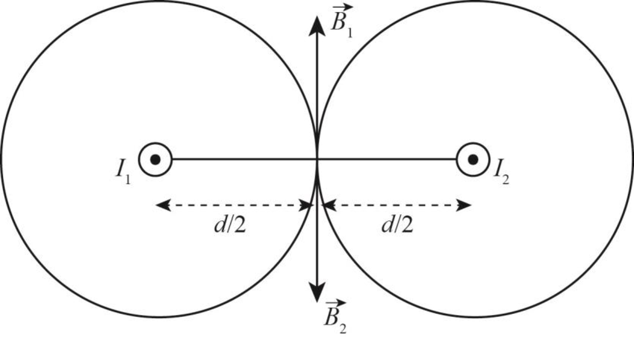
Figure-(1)
Write the expression to obtain the magnetic field due to the wire
Here,
Substitute
Write the expression to obtain the magnetic field due to the wire
Here,
Substitute
Write the expression to obtain the net magnetic field at the mid way between the wires.
Here,
Conclusion:
Substitute
Substitute
Substitute
Therefore, the magnitude is
(b)
The magnitude and the direction of the net magnetic field at point
(b)
Answer to Problem 20P
The magnitude of net magnetic field at point
Explanation of Solution
The net magnetic field at point
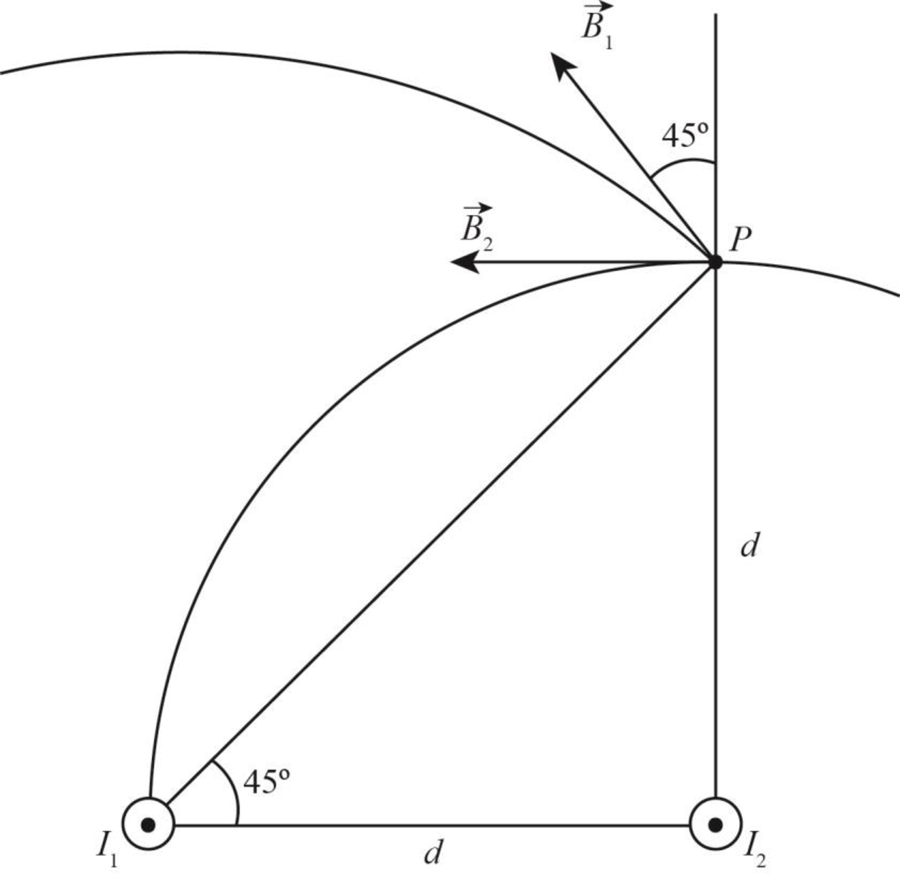
Figure-(2)
Write the expression to obtain the magnetic field due to the wire
Here,
Substitute
Write the expression to obtain the magnetic field due to the wire
Here,
Substitute
Write the expression to obtain the net magnetic field at the distance
Here,
Write the expression to obtain the magnitude of the net magnetic field at the distance
Here,
Write the expression to obtain direction of the net magnetic field at point
Here,
Conclusion:
Substitute
The value of
Substitute
Substitute
The value of
Substitute
Substitute
Substitute
Substitute
Therefore, the magnitude of net magnetic field at point
Want to see more full solutions like this?
Chapter 30 Solutions
Physics: for Science.. With Modern. -Update (Looseleaf)


- Two infinitely long current-carrying wires run parallel in the xy plane and are each a distance d = 11.0 cm from the y axis (Fig. P30.83). The current in both wires is I = 5.00 A in the negative y direction. a. Draw a sketch of the magnetic field pattern in the xz plane due to the two wires. What is the magnitude of the magnetic field due to the two wires b. at the origin and c. as a function of z along the z axis, at x = y = 0? FIGURE P30.83arrow_forwardA circular coil 15.0 cm in radius and composed of 145 tightly wound turns carries a current of 2.50 A in the counterclockwise direction, where the plane of the coil makes an angle of 15.0 with the y axis (Fig. P30.73). The coil is free to rotate about the z axis and is placed in a region with a uniform magnetic field given by B=1.35jT. a. What is the magnitude of the magnetic torque on the coil? b. In what direction will the coil rotate? FIGURE P30.73arrow_forwardA wire is bent in the form of a square loop with sides of length L (Fig. P30.24). If a steady current I flows in the loop, determine the magnitude of the magnetic field at point P in the center of the square. FIGURE P30.24arrow_forward
- Within the green dashed circle show in Figure P30.21, the magnetic field changes with time according to the expression B = 2.00t3 4.00t2 + 0.800, where B is in teslas, t is in seconds, and R = 2.50 cm. When t = 2.00 s, calculate (a) the magnitude and (b) the direction of the force exerted on an electron located at point P, which is at a distance r = 5.00 cm from the center of the circular field region. (c) At what instant is this force equal to zero? Figure P30.21arrow_forwardA metal rod of mass m slides without friction along two parallel horizontal rails, separated by a distance and connected by a resistor R, as shown in Figure P30.13. A uniform vertical magnetic field of magnitude B is applied perpendicular to the plane of the paper. The applied force shown in the figure acts only for a moment, to give the rod a speed v. In terms of m, , R, B, and v, find the distance the rod will then slide as it coasts to a stop. Figure P30.13arrow_forwardFigure P30.10 shows a circular current-carrying wire. Using the coordinate system indicated (with the z axis out of the page), state the direction of the magnetic field at points A and B.arrow_forward
- For both sketches in Figure P30.56, there is a 3.54-A current, a magnetic field strength B 0.650 T. and the angle is 32.0. Find the magnetic force per unit length (magnitude and direction) exerted on the current-carrying conductor in both cases.arrow_forwardIn Figure P22.43, the current in the long, straight wire is I1 = 5.00 A and the wire lies in the plane of the rectangular loop, which carries a current I2 = 10.0 A. The dimensions in the figure are c = 0.100 m, a = 0.150 m, and = 0.450 m. Find the magnitude and direction of the net force exerted on the loop by the magnetic field created by the wire. Figure P22.43 Problems 43 and 44.arrow_forwardTwo long, straight, parallel wires carry currents that are directed perpendicular to the page as shown in Figure P30.9. Wire 1 carries a current I1, into the page (in the negative z direction) and passes through the x axis at x = +. Wire 2 passes through the x axis at x = 2a and carries an unknown current I2. The total magnetic field at the origin due to the current-carrying wires has the magnitude 20I1(2a). The current I2 can have either of two possible values, (a) Find the value of with the smaller magnitude, stating it in terms of I1, and giving its direction. (b) Find the other possible value of I2.arrow_forward
 Physics for Scientists and Engineers: Foundations...PhysicsISBN:9781133939146Author:Katz, Debora M.Publisher:Cengage Learning
 Principles of Physics: A Calculus-Based TextPhysicsISBN:9781133104261Author:Raymond A. Serway, John W. JewettPublisher:Cengage Learning
 Physics for Scientists and Engineers, Technology ...PhysicsISBN:9781305116399Author:Raymond A. Serway, John W. JewettPublisher:Cengage Learning
 Physics for Scientists and EngineersPhysicsISBN:9781337553278Author:Raymond A. Serway, John W. JewettPublisher:Cengage Learning
 Physics for Scientists and Engineers with Modern ...PhysicsISBN:9781337553292Author:Raymond A. Serway, John W. JewettPublisher:Cengage Learning