Videos
A
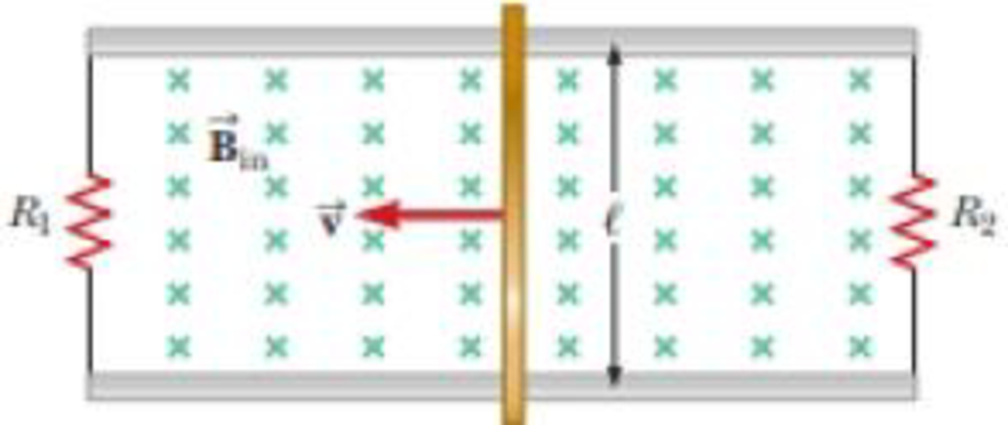
Figure P30.35

Trending nowThis is a popular solution!

Chapter 30 Solutions
Bundle: Physics For Scientists And Engineers With Modern Physics, 10th + Webassign Printed Access Card For Serway/jewett's Physics For Scientists And Engineers, 10th, Multi-term
Additional Science Textbook Solutions
Schaum's Outline of College Physics, Twelfth Edition (Schaum's Outlines)
Physics of Everyday Phenomena
The Cosmic Perspective (9th Edition)
Glencoe Physical Science 2012 Student Edition (Glencoe Science) (McGraw-Hill Education)


- In Figure P30.38, the rolling axle, 1.50 m long, is pushed along horizontal rails at a constant speed v = 3.00 m/s. A resistor R = 0.400 is connected to the rails at points a and b, directly opposite each other. The wheels make good electrical contact with the rails, so the axle, rails, and R form a closed-loop circuit. The only significant resistance in the circuit is R. A uniform magnetic field B = 0.080 0 T is vertically downward. (a) Find the induced current I in the resistor. (b) What horizontal force F is required to keep the axle rolling at constant speed? (c) Which end of the resistor, a or b, is at the higher electric potential? (d) What If? After the axle rolls past the resistor, does the current in R reverse direction? Explain your answer. Figure P30.38arrow_forwardA rectangular coil consists of N = 100 closely wrapped turns and has dimensions a = 0.400 m and b = 0.300 m. The coil is hinged along the y axis, and its plane makes an angle = 30.0 with the x axis (Fig. P22.25). (a) What is the magnitude of the torque exerted on the coil by a uniform magnetic field B = 0.800 T directed in the positive x direction when the current is I = 1.20 A in the direction shown? (b) What is the expected direction of rotation of the coil? Figure P22.25arrow_forwardA circular coil 15.0 cm in radius and composed of 145 tightly wound turns carries a current of 2.50 A in the counterclockwise direction, where the plane of the coil makes an angle of 15.0 with the y axis (Fig. P30.73). The coil is free to rotate about the z axis and is placed in a region with a uniform magnetic field given by B=1.35jT. a. What is the magnitude of the magnetic torque on the coil? b. In what direction will the coil rotate? FIGURE P30.73arrow_forward
- A piece of insulated wire is shaped into a figure eight as shown in Figure P23.12. For simplicity, model the two halves of the figure eight as circles. The radius of the upper circle is 5.00 cm and that of the lower circle is 9.00 cm. The wire has a uniform resistance per unit length of 3.00 Ω/m. A uniform magnetic field is applied perpendicular to the plane of the two circles, in the direction shown. The magnetic field is increasing at a constant rate of 2.00 T/s. Find (a) the magnitude and (b) the direction of the induced current in the wire. Figure P23.12arrow_forwardA wire is bent in the form of a square loop with sides of length L (Fig. P30.24). If a steady current I flows in the loop, determine the magnitude of the magnetic field at point P in the center of the square. FIGURE P30.24arrow_forwardA circular loop of wire of resistance R = 0.500 and radius r = 8.00 cm is in a uniform magnetic field directed out of the page as in Figure P31.54. If a clockwise current of I = 2.50 mA is induced in the loop, (a) is the magnetic field increasing or decreasing in time? (b) Find the rate at which the field is changing with time. Figure P31.54arrow_forward
- Consider the apparatus shown in Figure P30.32: a conducting bar is moved along two rails connected to an incandescent lightbulb. The whole system is immersed in a magnetic field of magnitude B = 0.400 T perpendicular and into the page. The distance between the horizontal rails is = 0.800 m. The resistance of the lightbulb is R = 48.0 , assumed to be constant. The bar and rails have negligible resistance. The bar is moved toward the right by a constant force of magnitude F = 0.600 N. We wish to find the maximum power delivered to the lightbulb. (a) Find an expression for the current in the lightbulb as a function of B, , R, and v, the speed of the bar. (b) When the maximum power is delivered to the lightbulb, what analysis model properly describes the moving bar? (c) Use the analysis model in part (b) to find a numerical value for the speed v of the bar when the maximum power is being delivered to the lightbulb. (d) Find the current in the lightbulb when maximum power is being delivered to it. (e) Using P = I2R, what is the maximum power delivered to the lightbulb? (f) What is the maximum mechanical input power delivered to the bar by the force F? (g) We have assumed the resistance of the lightbulb is constant. In reality, as the power delivered to the lightbulb increases, the filament temperature increases and the resistance increases. Does the speed found in part (c) change if the resistance increases and all other quantities are held constant? (h) If so, does the speed found in part (c) increase or decrease? If not, explain. (i) With the assumption that the resistance of the lightbulb increases as the current increases, does the power found in part (f) change? (j) If so, is the power found in part (f) larger or smaller? If not, explain. Figure P30.32arrow_forwardIn Figure P20.65 the rolling axle of length 1.50 m is pushed along horizontal rails at a constant speed v = 3.00 m/s. A resist or R = 0.400 is connected to the rails at points a and b, directly opposite each other. (The wheels make good electrical contact with the rails, so the axle, rails, and R form a closed-loop circuit. The only significant resistance in the circuit is R.) A uniform magnetic field B = 0.800 T is directed vertically downward. (a) Find the induced current I in the resistor. (b) What horizontal force F is required to keep the axle rolling at constant speed? (c) Which end of the resistor, a or b. is at the higher electric potential? (d) Alter the axle rolls past the resistor, does the current in R reverse direction? Explain your answer. Figure P20.65arrow_forwardA metal rod of mass m slides without friction along two parallel horizontal rails, separated by a distance and connected by a resistor R, as shown in Figure P30.13. A uniform vertical magnetic field of magnitude B is applied perpendicular to the plane of the paper. The applied force shown in the figure acts only for a moment, to give the rod a speed v. In terms of m, , R, B, and v, find the distance the rod will then slide as it coasts to a stop. Figure P30.13arrow_forward
- A constant magnetic field of 0.275 T points through a circular loop of wire with radius 3.50 cm as shown in Figure P32.1. a. What is the magnetic flux through the loop? b. Is a current induced in the loop? Explain. FIGURE P32.1arrow_forwardConsider the system pictured in Figure P28.26. A 15.0-cm horizontal wire of mass 15.0 g is placed between two thin, vertical conductors, and a uniform magnetic field acts perpendicular to the page. The wire is free to move vertically without friction on the two vertical conductors. When a 5.00-A current is directed as shown in the figure, the horizontal wire moves upward at constant velocity in the presence of gravity. (a) What forces act on the horizontal wire, and (b) under what condition is the wire able to move upward at constant velocity? (c) Find the magnitude and direction of the minimum magnetic Field required to move the wire at constant speed. (d) What happens if the magnetic field exceeds this minimum value? Figure P28.26arrow_forwardFigure P23.15 shows a top view of a bar that can slide on two frictionless rails. The resistor is R = 6.00 , and a 2.50-T magnetic field is directed perpendicularly downward, into the paper. Let = 1.20 m. (a) Calculate the applied force required to move the bar to the right at a constant speed of 2.00 m/s. (b) At what rate is energy delivered to the resistor? Figure P23.15 Problems 15 through 18.arrow_forward
 Physics for Scientists and Engineers with Modern ...PhysicsISBN:9781337553292Author:Raymond A. Serway, John W. JewettPublisher:Cengage Learning
 Principles of Physics: A Calculus-Based TextPhysicsISBN:9781133104261Author:Raymond A. Serway, John W. JewettPublisher:Cengage Learning
 Physics for Scientists and EngineersPhysicsISBN:9781337553278Author:Raymond A. Serway, John W. JewettPublisher:Cengage Learning
 Physics for Scientists and Engineers, Technology ...PhysicsISBN:9781305116399Author:Raymond A. Serway, John W. JewettPublisher:Cengage Learning
 College PhysicsPhysicsISBN:9781305952300Author:Raymond A. Serway, Chris VuillePublisher:Cengage Learning
 College PhysicsPhysicsISBN:9781285737027Author:Raymond A. Serway, Chris VuillePublisher:Cengage Learning