
Videos
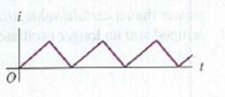
A Differentiating Circuit. The current in a resistanceless inductor is caused to vary with time as shown in the graph of Fig. Q30.10. (a) Sketch the pattern that would be observed on the screen of an oscilloscope connected to the terminals of the inductor. (The oscilloscope spot sweeps horizontally across the screen at a constant speed, and its vertical deflection is proportional to the potential difference between the inductor terminals.) (b) Explain why a circuit with an inductor can be described as a “differentiating circuit.”
Figure Q30.10
Want to see the full answer?
Check out a sample textbook solution
Chapter 30 Solutions
University Physics, Volume 2 - Technology Update Custom Edition for Texas A&M - College Station, 2/e
Additional Science Textbook Solutions
University Physics with Modern Physics (14th Edition)
College Physics
Essential University Physics: Volume 1 (3rd Edition)
College Physics
Physics for Scientists and Engineers: A Strategic Approach, Vol. 1 (Chs 1-21) (4th Edition)
College Physics: A Strategic Approach (4th Edition)


- When a wire carries an AC current with a known frequency, you can use a Rogowski coil to determine the amplitude Imax of the current without disconnecting the wire to shunt the current through a meter. The Rogowski coil, shown in Figure P23.8, simply clips around the wire. It consists of a toroidal conductor wrapped around a circular return cord. Let n represent the number of turns in the toroid per unit distance along it. Let A represent the cross-sectional area of the toroid. Let I(t) = Imax sin t represent the current to be measured. (a) Show that the amplitude of the emf induced in the Rogowski coil is Emax=0nAImax. (b) Explain why the wire carrying the unknown current need not be at the center of the Rogowski coil and why the coil will not respond to nearby currents that it does not enclose. Figure P23.8arrow_forwardAt t = 0, the open switch in Figure P31.46 is thrown closed. We wish to find a symbolic expression for the current in the inductor for time t 0. Let this current be called i and choose it to be downward in the inductor in Figure P31.46. Identify i1 as the current to the right through R1 and i2 as the current downward through R2. (a) Use Kirchhoffs junction rule to find a relation among the three currents. (b) Use Kirchhoffs loop rule around the left loop to find another relationship. (c) Use Kirchhoffs loop rule around the outer loop to find a third relationship. (d) Eliminate i1 and i2 among the three equations to find an equation involving only the current i. (e) Compare the equation in part (d) with Equation 31.6 in the text. Use this comparison to rewrite Equation 31.7 in the text for the situation in this problem and show that i(t)=R1[1e(R/L)t] where R = R1R2/(R1 + R2). Figure P31.46arrow_forwardReview. In Figure P30.42, a uniform magnetic field decreases at a constant rate dB/dt = K, where K is a positive constant. A circular loop of wire of radius a containing a resistance R and a capacitance C is placed with its plane normal to the field. (a) Find the charge Q on the capacitor when it is fully charged. (b) Which plate, upper or lower, is at the higher potential? (c) Discuss the force that causes the separation of charges. Figure P30.42arrow_forward
 Physics for Scientists and Engineers: Foundations...PhysicsISBN:9781133939146Author:Katz, Debora M.Publisher:Cengage Learning
 Principles of Physics: A Calculus-Based TextPhysicsISBN:9781133104261Author:Raymond A. Serway, John W. JewettPublisher:Cengage Learning
 Physics for Scientists and Engineers, Technology ...PhysicsISBN:9781305116399Author:Raymond A. Serway, John W. JewettPublisher:Cengage Learning
 Physics for Scientists and Engineers with Modern ...PhysicsISBN:9781337553292Author:Raymond A. Serway, John W. JewettPublisher:Cengage Learning
 Physics for Scientists and EngineersPhysicsISBN:9781337553278Author:Raymond A. Serway, John W. JewettPublisher:Cengage Learning
 College PhysicsPhysicsISBN:9781285737027Author:Raymond A. Serway, Chris VuillePublisher:Cengage Learning