
Videos
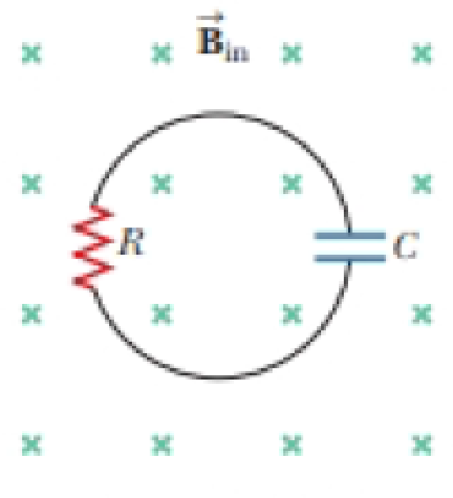
Review. In Figure P30.42, a uniform magnetic field decreases at a constant rate dB/dt = −K, where K is a positive constant. A circular loop of wire of radius a containing a resistance R and a capacitance C is placed with its plane normal to the field. (a) Find the charge Q on the capacitor when it is fully charged. (b) Which plate, upper or lower, is at the higher potential? (c) Discuss the force that causes the separation of charges.
Figure P30.42

Trending nowThis is a popular solution!

Chapter 30 Solutions
Physics for Scientists and Engineers with Modern Physics
Additional Science Textbook Solutions
EBK FUNDAMENTALS OF THERMODYNAMICS, ENH
Conceptual Physics (12th Edition)
Essential University Physics: Volume 1 (3rd Edition)
Physics for Scientists and Engineers with Modern Physics
MODERN PHYSICS (LOOSELEAF)
University Physics Volume 2


- A loop of wire in the shape of a rectangle of width w and length L and a long, straight wire carrying a current I lie on a tabletop as shown in Figure P23.7. (a) Determine the magnetic flux through the loop due to the current I. (b) Suppose the current is changing with time according to I = a + bt, where a and b are constants. Determine the emf that is induced in the loop if b = 10.0 A/s, h = 1.00 cm, w = 10.0 cm, and L = 1.00 m. (c) What is the direction of the induced current in the rectangle? Figure P23.7arrow_forwardFigure P30.39 shows a stationary conductor whose shape is similar to the letter e. The radius of its circular portion is a = 50.0 cm. It is placed in a constant magnetic field of 0.500 T directed out of the page. A straight conducting rod, 50.0 cm long, is pivoted about point O and rotates with a constant angular speed of 2.00 rad/s. (a) Determine the induced emf in the loop POQ. Note that the area of the loop is a2/2. (b) If all the conducting material has a resistance per length of 5.00 /m, what is the induced current in the loop POQ at the instant 0.250 s after point P passes point Q? Figure P30.39arrow_forwardReview. The bar of mass m in Figure P30.51 is pulled horizontally across parallel, frictionless rails by a massless string that passes over a light, frictionless pulley and is attached to a suspended object of mass M. The uniform upward magnetic field has a magnitude B, and the distance between the rails is . The only significant electrical resistance is the load resistor R shown connecting the rails at one end. Assuming the suspended object is released with the bar at rest at t = 0, derive an expression that gives the bars horizontal speed as a function of time. Figure P30.51arrow_forward
- In Figure P30.38, the rolling axle, 1.50 m long, is pushed along horizontal rails at a constant speed v = 3.00 m/s. A resistor R = 0.400 is connected to the rails at points a and b, directly opposite each other. The wheels make good electrical contact with the rails, so the axle, rails, and R form a closed-loop circuit. The only significant resistance in the circuit is R. A uniform magnetic field B = 0.080 0 T is vertically downward. (a) Find the induced current I in the resistor. (b) What horizontal force F is required to keep the axle rolling at constant speed? (c) Which end of the resistor, a or b, is at the higher electric potential? (d) What If? After the axle rolls past the resistor, does the current in R reverse direction? Explain your answer. Figure P30.38arrow_forwardA metal rod of mass m slides without friction along two parallel horizontal rails, separated by a distance and connected by a resistor R, as shown in Figure P30.13. A uniform vertical magnetic field of magnitude B is applied perpendicular to the plane of the paper. The applied force shown in the figure acts only for a moment, to give the rod a speed v. In terms of m, , R, B, and v, find the distance the rod will then slide as it coasts to a stop. Figure P30.13arrow_forwardThe magnetic field through a square loop of wire with sides of length 3.00 cm changes with time as shown in Figure P32.8, where the sign indicates the direction of the field relative to the axis of the loop. Plot the emf induced in the loop versus time. FIGURE P32.8arrow_forward
- Review. Figure P31.31 shows a bar of mass m that can slide without friction on a pair of rails separated by a distance and located on an inclined plane that makes an angle with respect to the ground. The resistance of the resistor is R. and a uniform magnetic field of magnitude H is directed downward, perpendicular to the ground, over the entire region through which the bar moves. With what constant speed v does the bar slide along the rails?arrow_forwardA metal rod of mass M and length L is pivoted about a hinge at point O as shown in Figure P32.80. The axis of rotation passes through O into the page. A constant magnetic field B is applied into the page. Find the ratio of the maximum electric field inside the rod to the applied magnetic field when the rod is rotated with angular speed . Assume the speed of the rod is determined by the linear speed of its center of mass, and its mass is uniformly distributed. FIGURE P32.80arrow_forwardA wire is bent in the form of a square loop with sides of length L (Fig. P30.24). If a steady current I flows in the loop, determine the magnitude of the magnetic field at point P in the center of the square. FIGURE P30.24arrow_forward
- A circular coil 15.0 cm in radius and composed of 145 tightly wound turns carries a current of 2.50 A in the counterclockwise direction, where the plane of the coil makes an angle of 15.0 with the y axis (Fig. P30.73). The coil is free to rotate about the z axis and is placed in a region with a uniform magnetic field given by B=1.35jT. a. What is the magnitude of the magnetic torque on the coil? b. In what direction will the coil rotate? FIGURE P30.73arrow_forwardA bar magnet is held in a vertical orientation above a loop of wire that lies in the horizontal plane as shown in Figure OQ23.13. The south end of the magnet is toward the loop. After the magnet is dropped, what is true of the induced current in the loop as viewed from above? (a) It is clockwise as the magnet falls toward the loop. (b) It is counterclockwise as the magnet falls toward the loop. (c) It is clockwise after the magnet has moved through the loop and moves away from it. (d) It is always clockwise. (e) It is first counterclockwise as the magnet approaches the loop and then clockwise after it has passed through the loop.arrow_forwardA conducting rod of length moves with velocity v parallel to a long wire carrying a steady current I. The axis of the rod is maintained perpendicular to the wire with the near end a distance r away (Fig. P30.44). Show that the magnitude of the emf induced in the rod is E=0Iv2ln(1+lr) Figure P30.44arrow_forward
 Physics for Scientists and Engineers with Modern ...PhysicsISBN:9781337553292Author:Raymond A. Serway, John W. JewettPublisher:Cengage Learning
 Physics for Scientists and EngineersPhysicsISBN:9781337553278Author:Raymond A. Serway, John W. JewettPublisher:Cengage Learning
 Physics for Scientists and Engineers: Foundations...PhysicsISBN:9781133939146Author:Katz, Debora M.Publisher:Cengage Learning
 Principles of Physics: A Calculus-Based TextPhysicsISBN:9781133104261Author:Raymond A. Serway, John W. JewettPublisher:Cengage Learning
 Physics for Scientists and Engineers, Technology ...PhysicsISBN:9781305116399Author:Raymond A. Serway, John W. JewettPublisher:Cengage Learning