
Videos
Figure 31-19 shows three oscillating LC circuits with identical inductors and capacitors At a particular time, the charges on the capacitor plates (and thus the electric fields between the plates) are all at their maximum values Rank the circuits according to the time taken to fully discharge the capacitors during the oscillations, greatest first.
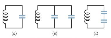
Figure 31-19 Question 1.
To find:
The rank of the circuits according to the time taken to fully discharge the capacitors during the oscillations.
Answer to Problem 1Q
Solution:
The rank of the circuits according to time taken to fully discharge the capacitors during the oscillations is circuit b, circuit a, circuit c.
Explanation of Solution
1) Concept:
The charging and discharging of a capacitor in a LC circuit is like an oscillatory motion. The period of these oscillations depends upon the values of the inductance and the capacitance in the circuit.
2) Formula:
i)
ii)
3) Given:
i) The inductors and capacitors in the three circuits are identical.
ii) The two capacitors in the circuit b are in parallel combination.
iii) The two capacitors in the circuit c are in series combination.
4) Calculations:
a) Consider circuit b. The two capacitors are connected in parallel combination. Hence the effective capacitance of the circuit is
Since both the capacitors are identical, the effective capacitance is
b) Now, consider circuit c. The two capacitors are connected in series combination. Hence the effective capacitance of the circuit is
Since both the capacitors are identical, the effective capacitance is
c) The period of oscillations is calculated using the equation
and
i.e.,
Thus, we see that
But since the inductors in the three circuits are identical,
Now, for circuit b, the effective capacitance is greatest among the three. Hence its period is also the greatest. Thus, time for the capacitor to discharge fully, which is
For circuit a, the capacitance is C, which is smaller than that for circuit b. Hence the time for the discharge will also be smaller.
For circuit c, the effective capacitance is the smallest among the three. Hence the time required for complete discharge will also be the smallest.
Thus the ranks for the circuits are circuit b, circuit a, and then circuit c.
Conclusion:
The time required for the capacitor to discharge fully is
Want to see more full solutions like this?
Chapter 31 Solutions
WILEY ETEXT FUND. OF PHYSICS +WEBASSIGN
Additional Science Textbook Solutions
Applied Physics (11th Edition)
Physics (5th Edition)
College Physics: A Strategic Approach (3rd Edition)
College Physics: A Strategic Approach (4th Edition)
Sears And Zemansky's University Physics With Modern Physics
Physics for Scientists and Engineers: A Strategic Approach with Modern Physics (4th Edition)


- For an LC circuit, show that the total energy stored in the electric and magnetic fields is a constant given by Equation 33.28, Etot=Qmax2/2C=12LImax2.arrow_forwardIn an oscillating LC circuit with L = 50 mH and C = 4.0 mF, the current is initially a maximum. How long will it take before the capacitor is fully charged for the first time?arrow_forwardAn LC circuit has an inductor of inductance 8.4 mH and a capacitor with a capacitance of 963.7 µF. At what frequency, in radians per second, will the circuit oscillate?arrow_forward
- The self-inductance and capacitance of an LC circuit e 0.20 mH and 5.0 pF. What is the angular frequency at which the circuit oscillates?arrow_forwardAt s1iat frequency is the reactance of a 20F capacitor equal to that of a 10-mH inductor?arrow_forwardIn the LC circuit in Figure 33.11, the inductance is L = 19.8 mH and the capacitance is C = 19.6 mF. At some moment, UB = UE= 17.5 mJ. a. What is the maximum charge stored by the capacitor? b. What is the maximum current in the circuit? c. At t = 0, the capacitor is fully charged. Write an expression for the charge stored by the capacitor as a function of lime. d. Write an expression for the current as a function of time.arrow_forward
- At 1000 Hz, the reactance of a 5.0-mH inductor is equal to the reactance of a particular capacitor. What is the capacitance of the capacitor?arrow_forwardThe frequency of oscillation of a certain LC circuit is 200 kHz.At time t = 0, plate A of the capacitor has maximum positive charge. At what earliest time t > 0 will (a) plate A again have maximum positive charge, (b) the other plate of the capacitor have maximum positive charge, and (c) the inductor have maximum magnetic field?arrow_forwardThe frequency of oscillation of a certain LC circuit is 168 kHz. At time t = 0, plate A of the capacitor has maximum positive charge. At what earliest time t > 0 will (a) plate A again have maximum positive charge, (b) the other plate of the capacitor have maximum positive charge, and (c) the inductor have maximum magnetic field?arrow_forward

 Physics for Scientists and Engineers: Foundations...PhysicsISBN:9781133939146Author:Katz, Debora M.Publisher:Cengage Learning
 Classical Dynamics of Particles and SystemsPhysicsISBN:9780534408961Author:Stephen T. Thornton, Jerry B. MarionPublisher:Cengage Learning