Videos
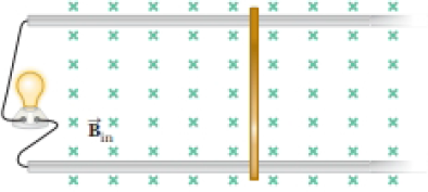
Consider the apparatus shown in Figure P30.32: a
Figure P30.32
(a)
Answer to Problem 31.58AP
Explanation of Solution
Given info: Magnetic field of system is
The emf develop in the system can be given as,
Here,
The current developed in the bar can be given as,
Here,
Substitute
Thus, the expression for current is
Conclusion:
Therefore, the expression for current as a function of
(b)
Answer to Problem 31.58AP
Explanation of Solution
Given info: Magnetic field of system is
The power delivered to the light bulb can be given as,
Here,
As the power is function of both force and speed, in order to maximize the power both force and velocity needs to be maximum. The desired condition can only be achieved if there is loss of energy whatsoever which can only be possible if the particle is in equilibrium.
Thus, the analysis model which describes the moving bar for maximum power is particle under equilibrium.
Conclusion:
Therefore, the analysis model which describes the moving bar for maximum power is particle under equilibrium.
(c)
Answer to Problem 31.58AP
Explanation of Solution
Given info: Magnetic field of system is
The magnetic force applied on the bar can be given as,
Substitute
Rearrange the above equation for
Substitute
Thus, the speed of the bar is
Conclusion:
Therefore, the speed of the bar when maximum power is delivered to the light bulb is
(d)
Answer to Problem 31.58AP
Explanation of Solution
Given info: Magnetic field of system is
The current in the light bulb can be given as from equation (1),
Substitute
Thus, the current in light bulb is
Conclusion:
Therefore, the current in light bulb when maximum power is delivered is
(e)
Answer to Problem 31.58AP
Explanation of Solution
Given info: Magnetic field of system is
The power delivered to the light bulb can be given as,
Substitute
Thus, the maximum power delivered to the light bulb is
Conclusion:
Therefore, the maximum power delivered to the light bulb will be
(f)
Answer to Problem 31.58AP
Explanation of Solution
Given info: Magnetic field of system is
The mechanical input power can be given as,
Substitute
Thus, the maximum mechanical input power is
Conclusion:
The maximum mechanical input power delivered to the bar is
(g)
Answer to Problem 31.58AP
Explanation of Solution
Given info: Magnetic field of system is
Consider the expression for speed of the bar from equation (2).
As speed of the bar depends on the resistance, therefore it will change if the resistance increases.
Conclusion:
Therefore, the velocity will change if the resistance increases.
(h)
Answer to Problem 31.58AP
Explanation of Solution
Given info: Magnetic field of system is
Consider the expression for speed of the bar from equation (2),
From the above equation, the speed will be directly proportional to the resistance if all other variables are held constant.
Thus, the speed of the bar will increase if resistance increases.
Conclusion:
Therefore, the speed of the bar will increase if the resistance increases.
(i)
Answer to Problem 31.58AP
Explanation of Solution
Given info: Magnetic field of system is
As far as the mechanical power input is concerned it only depends on the load and the velocity of the object. Since the current in electrical machinery is analogous to mechanical load, an increase in current will lead to change in mechanical load which further changes the mechanical power input.
Thus, the mechanical power input will change.
Conclusion:
Therefore, the effect of increase in resistance and current on the mechanical power input is that it will change.
(j)
Answer to Problem 31.58AP
Explanation of Solution
Given info: Magnetic field of system is
Both current and resistance can never increase as it violates Ohm’s law which says that current is inversely proportional to resistance.
In order to increase current despite increase in resistance, the load demand will increase to increase the current supply, this further increases the power.
Thus, the mechanical power input will increase if both current and resistance will increase.
Conclusion:
Thus, the mechanical power input will increase if both current and resistance will increase.
Want to see more full solutions like this?
Chapter 31 Solutions
Physics For Scientists And Engineers, Technology Update, Loose-leaf Version


- A metal rod of mass m slides without friction along two parallel horizontal rails, separated by a distance and connected by a resistor R, as shown in Figure P30.13. A uniform vertical magnetic field of magnitude B is applied perpendicular to the plane of the paper. The applied force shown in the figure acts only for a moment, to give the rod a speed v. In terms of m, , R, B, and v, find the distance the rod will then slide as it coasts to a stop. Figure P30.13arrow_forwardA wire is bent in the form of a square loop with sides of length L (Fig. P30.24). If a steady current I flows in the loop, determine the magnitude of the magnetic field at point P in the center of the square. FIGURE P30.24arrow_forwardA circular coil 15.0 cm in radius and composed of 145 tightly wound turns carries a current of 2.50 A in the counterclockwise direction, where the plane of the coil makes an angle of 15.0 with the y axis (Fig. P30.73). The coil is free to rotate about the z axis and is placed in a region with a uniform magnetic field given by B=1.35jT. a. What is the magnitude of the magnetic torque on the coil? b. In what direction will the coil rotate? FIGURE P30.73arrow_forward
- A loop of wire in the shape of a rectangle of width w and length L and a long, straight wire carrying a current I lie on a tabletop as shown in Figure P23.7. (a) Determine the magnetic flux through the loop due to the current I. (b) Suppose the current is changing with time according to I = a + bt, where a and b are constants. Determine the emf that is induced in the loop if b = 10.0 A/s, h = 1.00 cm, w = 10.0 cm, and L = 1.00 m. (c) What is the direction of the induced current in the rectangle? Figure P23.7arrow_forwardWhy is the following situation impossible? A conducting rectangular loop of mass M = 0.100 kg, resistance R = 1.00 , and dimensions w = 50.0 cm by = 90.0 cm is held with its lower edge just above a region with a uniform magnetic field of magnitude B = 1.00 T as shown in Figure P30.34. The loop is released from rest. Just as the top edge of the loop reaches the region containing the field, the loop moves with a speed 4.00 m/s. Figure P30.34arrow_forwardReview. The bar of mass m in Figure P30.51 is pulled horizontally across parallel, frictionless rails by a massless string that passes over a light, frictionless pulley and is attached to a suspended object of mass M. The uniform upward magnetic field has a magnitude B, and the distance between the rails is . The only significant electrical resistance is the load resistor R shown connecting the rails at one end. Assuming the suspended object is released with the bar at rest at t = 0, derive an expression that gives the bars horizontal speed as a function of time. Figure P30.51arrow_forward
- For both sketches in Figure P30.56, there is a 3.54-A current, a magnetic field strength B 0.650 T. and the angle is 32.0. Find the magnetic force per unit length (magnitude and direction) exerted on the current-carrying conductor in both cases.arrow_forwardA conducting rod of length = 35.0 cm is free to slide on two parallel conducting bars as shown in Figure P30.35. Two resistors R1 = 2.00 and R2 = 5.00 are connected across the ends of the bars to form a loop. A constant magnetic field B = 2.50 T is directed perpendicularly into the page. An external agent pulls the rod to the left with a constant speed of v = 8.00 m/s. Find (a) the currents in both resistors, (b) the total power delivered to the resistance of the circuit, and (c) the magnitude of the applied force that is needed to move the rod with this constant velocity. Figure P30.35arrow_forwardThe triangular loop of wire shown in Figure P30.62 carries a current of 0.125 A, and a uniform magnetic field of 0.250 T points toward the right. Determine the force on each segment of the wire (indicate magnitude and direction) and the net force on the triangular loop.arrow_forward
- A Figure P32.74 shows an N-turn rectangular coil of length a and width b entering a region of uniform magnetic field of magnitude Bout directed out of the page. The velocity of the coil is constant and is upward in the figure. The total resistance of the coil is R. What are the magnitude and direction of the magnetic force on the coil a. when only a portion of the coil has entered the region with the field, b. when the coil is completely embedded in the field, and c. as the coil begins to exit the region with the field?arrow_forwardThree long, current-carrying wires are parallel to one another and separated by a distance d. The magnitudes and directions of the currents are shown in Figure P30.91. Wires 1 and 3 are fixed, but wire 2 is free to move. Wire 2 is displaced to the right by a small distance x. Determine the net force (per unit length) acting on wire 2 and the angular frequency of the resulting oscillation. Assume the mass per unit length of wire 2 is and x d. FIGURE P30.91arrow_forwardFigure P30.39 shows a stationary conductor whose shape is similar to the letter e. The radius of its circular portion is a = 50.0 cm. It is placed in a constant magnetic field of 0.500 T directed out of the page. A straight conducting rod, 50.0 cm long, is pivoted about point O and rotates with a constant angular speed of 2.00 rad/s. (a) Determine the induced emf in the loop POQ. Note that the area of the loop is a2/2. (b) If all the conducting material has a resistance per length of 5.00 /m, what is the induced current in the loop POQ at the instant 0.250 s after point P passes point Q? Figure P30.39arrow_forward
 Physics for Scientists and EngineersPhysicsISBN:9781337553278Author:Raymond A. Serway, John W. JewettPublisher:Cengage Learning
 Physics for Scientists and Engineers with Modern ...PhysicsISBN:9781337553292Author:Raymond A. Serway, John W. JewettPublisher:Cengage Learning
 Principles of Physics: A Calculus-Based TextPhysicsISBN:9781133104261Author:Raymond A. Serway, John W. JewettPublisher:Cengage Learning
 Physics for Scientists and Engineers: Foundations...PhysicsISBN:9781133939146Author:Katz, Debora M.Publisher:Cengage Learning