
Videos
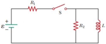
At t = 0, the open switch in Figure P31.46 is thrown closed. We wish to find a symbolic expression for the current in the inductor for time t > 0. Let this current be called i and choose it to be downward in the inductor in Figure P31.46. Identify i1 as the current to the right through R1 and i2 as the current downward through R2. (a) Use Kirchhoff’s junction rule to find a relation among the three currents. (b) Use Kirchhoff’s loop rule around the left loop to find another relationship. (c) Use Kirchhoff’s loop rule around the outer loop to find a third relationship. (d) Eliminate i1 and i2 among the three equations to find an equation involving only the current i. (e) Compare the equation in part (d) with Equation 31.6 in the text. Use this comparison to rewrite Equation 31.7 in the text for the situation in this problem and show that
where R′ = R1R2/(R1 + R2).
Figure P31.46
(a)
Answer to Problem 32.70AP
Explanation of Solution
Given info: The figure that shows the given circuit is shown below.
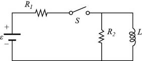
Figure (I)
According to Kirchhoff’s junction rule, the total incoming currents are equal to the total outgoing currents at a junction.
From the circuit diagram equating the incoming currents to the outgoing current,
Here,
Conclusion:
Therefore, the relation among three currents by Kirchhoff’s junction rule are
(b)
Answer to Problem 32.70AP
Explanation of Solution
Given info: The figure that shows the given circuit is shown in figure (I).
According to Kirchhoff’s loop rule, the sum of all the voltage across all the elements in a loop must be zero.
From the circuit diagram equating the voltage across the elements in the left loop is equal to zero.
Here,
Conclusion:
Therefore, the relationship between the given variables around the left loop by Kirchhoff’s loop rule is
(c)
Answer to Problem 32.70AP
Explanation of Solution
Given info: The figure that shows the given circuit is shown in figure (I).
According to Kirchhoff’s loop rule, the sum of all the voltage across all the elements in a loop must be zero.
From the circuit diagram equating the voltage across the elements in the outer loop is equal to zero.
Conclusion:
Therefore, the relationship between the given variables around the outer loop by Kirchhoff’s loop rule is
(d)
Answer to Problem 32.70AP
Explanation of Solution
Given info: The figure that shows the given circuit is shown in figure (I).
From equation (1), the expression for the
Substitute
From equation (2), the expression for the
Substitute
Equate equation (3) and equation (4) for
Further solve the above equation,
Assume
Substitute
Thus, the require equation in term of current
Conclusion:
Therefore, the equation that involve only current
(e)
Answer to Problem 32.70AP
Explanation of Solution
From the textbook the equation
From the part (d), the equation is given as,
Since both the equation shown above are same therefore their solution are also same.
The solution of the equation
Similarly rewrite the equation
Substitute
Conclusion:
Therefore, the equation
Want to see more full solutions like this?
Chapter 32 Solutions
EBK PHYSICS FOR SCIENTISTS AND ENGINEER


- A loop of wire in the shape of a rectangle of width w and length L and a long, straight wire carrying a current I lie on a tabletop as shown in Figure P23.7. (a) Determine the magnetic flux through the loop due to the current I. (b) Suppose the current is changing with time according to I = a + bt, where a and b are constants. Determine the emf that is induced in the loop if b = 10.0 A/s, h = 1.00 cm, w = 10.0 cm, and L = 1.00 m. (c) What is the direction of the induced current in the rectangle? Figure P23.7arrow_forwardA toroid having a rectangular cross section (a = 2.00 cm by b = 3.00 cm) and inner radius R = 4.00 cm consists of N = 500 turns of wire that carry a sinusoidal current I = Imax sin t, with Imax = 50.0 A and a frequency f = /2 = 60.0 Hz. A coil that consists of N = 20 turns of wire is wrapped around one section of the toroid as shown in Figure P30.9. Determine the emf induced in the coil as a function of time. Figure P30.9arrow_forwardFigure P30.39 shows a stationary conductor whose shape is similar to the letter e. The radius of its circular portion is a = 50.0 cm. It is placed in a constant magnetic field of 0.500 T directed out of the page. A straight conducting rod, 50.0 cm long, is pivoted about point O and rotates with a constant angular speed of 2.00 rad/s. (a) Determine the induced emf in the loop POQ. Note that the area of the loop is a2/2. (b) If all the conducting material has a resistance per length of 5.00 /m, what is the induced current in the loop POQ at the instant 0.250 s after point P passes point Q? Figure P30.39arrow_forward
- A rectangular toroid with inner radius R1= 7.0cm, outer radius R2= 9.0cm, height h = 3.0, and N=3.0, and N = 3000 turns is filled with an iron core a magnetic susceptibility 5.2 × 10³. (a) What is the self-inductance of the toroid? (b) If the current through the toroid is 2.0 A, what is the magnetic field at the center of the core? (c) For this same 2.0-A current, what is the effective surface current formed by the aligned atomic current loops in the iron core?arrow_forwardFigure P23.58 is a graph of the induced emf versus time for a coil of N turns rotating with angular speed ω in a uniform magnetic field directed perpendicular to the coil’s axis of rotation. What If? Copy this sketch (on a larger scale) and on the same set of axes show the graph of emf versus t (a) if the number of turns in the coil is doubled, (b) if instead the angular speed is doubled, and (c) if the angular speed is doubled while the number of turns in the coil is halved. Figure P23.58arrow_forwardAn aluminum ring of radius r1 = 5.00 cm and resistance 3.00 104 is placed around one end of a long air-core solenoid with 1 000 turns per meter and radius r2 = 3.00 cm as shown in Figure P30.5. Assume the axial component of the field produced by the solenoid is one-half as strong over the area of the end of the solenoid as at the center of the solenoid. Also assume the solenoid produces negligible field outside its cross-sectional area. The current in the solenoid is increasing at a rate of 270 A/s. (a) What is the induced current in the ring? At the center of the ring, what are (b) the magnitude and (c) the direction of the magnetic field produced by the induced current in the ring? Figure P30.5 Problems 5 and 6.arrow_forward
 Principles of Physics: A Calculus-Based TextPhysicsISBN:9781133104261Author:Raymond A. Serway, John W. JewettPublisher:Cengage Learning
 Physics for Scientists and EngineersPhysicsISBN:9781337553278Author:Raymond A. Serway, John W. JewettPublisher:Cengage Learning
 Physics for Scientists and Engineers with Modern ...PhysicsISBN:9781337553292Author:Raymond A. Serway, John W. JewettPublisher:Cengage Learning
 Physics for Scientists and Engineers, Technology ...PhysicsISBN:9781305116399Author:Raymond A. Serway, John W. JewettPublisher:Cengage Learning
 Physics for Scientists and Engineers: Foundations...PhysicsISBN:9781133939146Author:Katz, Debora M.Publisher:Cengage Learning