
Bundle: Physics for Scientists and Engineers, Volume 2, Loose-leaf Version, 10th + WebAssign Printed Access Card for Serway/Jewett's Physics for Scientists and Engineers, 10th, Multi-Term
10th Edition
ISBN: 9781337888752
Author: Raymond A. Serway; John W. Jewett
Publisher: Cengage Learning
expand_more
expand_more
format_list_bulleted
Videos
Textbook Question
Chapter 32, Problem 4P
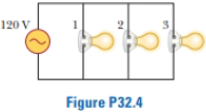
Figure P32.4 shows three lightbulbs connected to a 120-V AC (rms) household supply voltage. Bulbs 1 and 2 have a power rating of 150 W, and bulb 3 has a 100-W rating. Find (a) the rms current in each bulb and (b) the resistance of each bulb. (c) What is the total resistance of the combination of the three lightbulbs?
Figure P32.4
Expert Solution & Answer

Trending nowThis is a popular solution!

Students have asked these similar questions
An AC voltage source is connected to a resistor R = 1.05 102 Ω. The output from an AC voltage source is given by the expression V = (1.80 102 V) sin 2?ft.
(a) What is the rms voltage across the resistor? V(b) What is the rms current flowing through the resistor? A
An AC source operating at 60. Hz with a maximum voltage of170 V is connected in series with a resistor (R = 1.2 kΩ) anda capacitor (C 5 2.5 µF). (a) What is the maximum value ofthe current in the circuit? (b) What are the maximum valuesof the potential difference across the resistor and the capacitor?(c) When the current is zero, what are the magnitudesof the potential difference across the resistor, the capacitor,and the AC source? How much charge is on the capacitor atthis instant? (d) When the current is at a maximum, what arethe magnitudes of the potential differences across the resistor,the capacitor, and the AC source? How much charge is on thecapacitor at this instant?
VP31.3.3
An ac circuit includes a 155 Ω resistor in series with an 8.00 μF capacitor. The current in the circuit has amplitude 4.00×10⁻³ A. (a) Find the frequency for which the capacitive reactance equals the resistance. (b) At this frequency, what are the amplitudes of the voltages across the resistor and capacitor?
Chapter 32 Solutions
Bundle: Physics for Scientists and Engineers, Volume 2, Loose-leaf Version, 10th + WebAssign Printed Access Card for Serway/Jewett's Physics for Scientists and Engineers, 10th, Multi-Term
Ch. 32.2 - Consider the voltage phasor in Figure 32.4, shown...Ch. 32.3 - Consider the AC circuit in Figure 32.8. The...Ch. 32.4 - Consider the AC circuit in Figure 32.11. The...Ch. 32.4 - Consider the AC circuit in Figure 32.12. The...Ch. 32.5 - Label each part of Figure 32.16, (a), (b), and...Ch. 32.6 - An AC source drives an RLC circuit with a fixed...Ch. 32.7 - What is the impedance of a series RLC circuit at...Ch. 32 - (a) What is the resistance of a lightbulb that...Ch. 32 - A certain lightbulb is rated at 60.0 W when...Ch. 32 - The current in the circuit shown in Figure P32.3...
Ch. 32 - Figure P32.4 shows three lightbulbs connected to a...Ch. 32 - In the AC circuit shown in Figure P32.3, R = 70.0 ...Ch. 32 - In a purely inductive AC circuit as shown in...Ch. 32 - Prob. 7PCh. 32 - A 20.0-mH inductor is connected to a North...Ch. 32 - An AC source has an output rms voltage of 78.0 V...Ch. 32 - Review. Determine the maximum magnetic flux...Ch. 32 - A 1.00-mF capacitor is connected to a North...Ch. 32 - An AC source with an output rms voltage of 86.0 V...Ch. 32 - What is the maximum current in a 2.20-F capacitor...Ch. 32 - A capacitor C is connected to a power supply that...Ch. 32 - In addition to phasor diagrams showing voltages...Ch. 32 - An AC source with Vmax = 150 V and f = 50.0 Hz is...Ch. 32 - You are working in a factory and have been tasked...Ch. 32 - Prob. 18PCh. 32 - An RLC circuit consists of a 150- resistor, a...Ch. 32 - A 60.0-ft resistor is connected in series with a...Ch. 32 - A series RLC circuit has a resistance of 45.0 and...Ch. 32 - Prob. 22PCh. 32 - A series RLC circuit has a resistance of 22.0 and...Ch. 32 - An AC voltage of the form v = 90.0 sin 350t, where...Ch. 32 - The LC circuit of a radar transmitter oscillates...Ch. 32 - A series RLC circuit has components with the...Ch. 32 - You wish to build a series RLC circuit for a...Ch. 32 - A 10.0- resistor, 10.0-mH inductor, and 100-F...Ch. 32 - A resistor R, inductor L, and capacitor C are...Ch. 32 - The primary coil of a transformer has N1 = 350...Ch. 32 - A person is working near the secondary of a...Ch. 32 - A transmission line that has a resistance per unit...Ch. 32 - Prob. 33APCh. 32 - A 400- resistor, an inductor, and a capacitor are...Ch. 32 - Energy is to be transmitted over a pair of copper...Ch. 32 - Energy is to be transmitted over a pair of copper...Ch. 32 - A transformer may be used to provide maximum power...Ch. 32 - Show that the rms value for the sawtooth voltage...Ch. 32 - Marie Cornu, a physicist at the Polytechnic...Ch. 32 - A series RLC circuit has resonance angular...Ch. 32 - Review. One insulated conductor from a household...Ch. 32 - (a) Sketch a graph of the phase angle for an RLC...Ch. 32 - Prob. 43APCh. 32 - Review. In the circuit shown in Figure P32.44,...Ch. 32 - You have decided to build your own speaker system...Ch. 32 - A series RLC circuit is operating at 2.00 103 Hz....Ch. 32 - You are trying to become a member of the Physics...Ch. 32 - A series RLC circuit in which R = l.00 , L = 1.00...Ch. 32 - The resistor in Figure P32.49 represents the...Ch. 32 - An 80.0- resistor and a 200-mH inductor are...Ch. 32 - Prob. 51CP
Knowledge Booster


Learn more about
Need a deep-dive on the concept behind this application? Look no further. Learn more about this topic, physics and related others by exploring similar questions and additional content below.Similar questions
- The RC high-pass filter shown in Figure P33.53 has a resistance R = 0.500 and a capacitance C = 613 F. What is the ratio of the amplitude of the output voltage to that of the input voltage for this filter for a source frequency of 600 Hz?arrow_forwardIn the AC circuit shown in Figure P32.3, R = 70.0 and the output voltage of the AC source is Vmax sin t. (a) If VR = 0.250 Vmax for the first time at t = 0.0100 s, what is the angular frequency of the source? (b) What is the next value of t for which VR = 0.250 Vmax? Figure P32.6 Problem 3 and 5.arrow_forwardThe resistor in Figure P32.49 represents the midrange speaker in a three-speaker system. Assume its resistance to be constant at 8.00 . The source represents an audio amplifier producing signals of uniform amplitude Vmax = 10.0 V at all audio frequencies. The inductor and capacitor are to function as a band-pass filter with Vout/Vin=12 at 200 Hz and at 4.00 103 Hz. Determine the required values of (a) L and (b) C. Find (c) the maximum value of the ratio Vout/Vin; (d) the frequency fo at which the ratio has its maximum value; (e) the phase shift between vin and vout at 200 Hz, at fo, and at 4.00 103 Hz; and (f) the average power transferred to the speaker at 200 Hz, at f0, and at 4.00 103 Hz. (g) Recognizing that the diagram represents an RLC circuit driven by an AC source, find its quality factor. Figure P32.49arrow_forward
- An PLC series circuit with R=600 , L = 30 mH. and c=0.050F is driven by an ac source whose frequency and voltage amplitude are 500 Hz and 50 V, respectively, (a) What is the impedance of the circuit? (b) What is the amplitude of the current in the circuit? (c) What is the phase angle between the emf of the source and the current?arrow_forwardAn ac source of voltage amplitude 100 V and frequency 1.0 kHz drives an PLC series circuit with R=20, L = 4.0 mH, and C=50F . (a) Determine the rms current through the circuit, (b) What are the rms voltages across the three elements? (c) What is the phase angle between the emf and the current? (d) What is the power output of the source? (e) What is the power dissipated in the resistor?arrow_forwardAn AC source with Vmax = 150 V and f = 50.0 Hz is connected between points a and d in Figure P32.16. Calculate the maximum voltages between (a) points a and b, (b) points b and c, (c) points c and d, and (d) points b and d. Figure P32.16 Problems 16 and 51.arrow_forward
- In an RLC series circuit, the voltage amplitude and frequency of the source are 100 V and 500 Hz, respectively, an R = 5O0. L=0.20H, and C=2.0F . (a)What is the impedance of the circuit? (b) What is the amplitude of the current from the source? (C) If the emf of the source Is given by v(tt)=(100V)sin , how does the current vary with time? (d) Repeat the calculations with C changed to 0.20F .arrow_forwardIn a purely inductive AC circuit as shown in Figure P32.6, Vmax = 100 V. (a) The maximum current is 7.50 A at 50.0 Hz. Calculate the inductance L. (b) What If? At what angular frequency is the maximum current 2.50 A? Figure P32.6 Problem 6 and 7.arrow_forwardA capacitor and a resistor are connected in series across an AC source as shown in Figure OQ33.3. After the switch is closed, which of the following statements is true? (a) The voltage across the capacitor lags the current by 90. (b) The voltage across (lie resistor is out of phase with the current. (c) The voltage across the capacitor leads the current by 90. (d) The current decreases as the frequency of the source is increased, but its peak voltage remains the same. (e) None of those statements is correct.arrow_forward
arrow_back_ios
arrow_forward_ios
Recommended textbooks for you
 Physics for Scientists and Engineers with Modern ...PhysicsISBN:9781337553292Author:Raymond A. Serway, John W. JewettPublisher:Cengage Learning
 Physics for Scientists and EngineersPhysicsISBN:9781337553278Author:Raymond A. Serway, John W. JewettPublisher:Cengage Learning
 Physics for Scientists and Engineers: Foundations...PhysicsISBN:9781133939146Author:Katz, Debora M.Publisher:Cengage Learning
 College PhysicsPhysicsISBN:9781305952300Author:Raymond A. Serway, Chris VuillePublisher:Cengage Learning
 Glencoe Physics: Principles and Problems, Student...PhysicsISBN:9780078807213Author:Paul W. ZitzewitzPublisher:Glencoe/McGraw-Hill
 Physics for Scientists and Engineers, Technology ...PhysicsISBN:9781305116399Author:Raymond A. Serway, John W. JewettPublisher:Cengage Learning
Physics for Scientists and Engineers with Modern ...
Physics
ISBN:9781337553292
Author:Raymond A. Serway, John W. Jewett
Publisher:Cengage Learning
Physics for Scientists and Engineers
Physics
ISBN:9781337553278
Author:Raymond A. Serway, John W. Jewett
Publisher:Cengage Learning
Physics for Scientists and Engineers: Foundations...
Physics
ISBN:9781133939146
Author:Katz, Debora M.
Publisher:Cengage Learning
College Physics
Physics
ISBN:9781305952300
Author:Raymond A. Serway, Chris Vuille
Publisher:Cengage Learning
Glencoe Physics: Principles and Problems, Student...
Physics
ISBN:9780078807213
Author:Paul W. Zitzewitz
Publisher:Glencoe/McGraw-Hill
Physics for Scientists and Engineers, Technology ...
Physics
ISBN:9781305116399
Author:Raymond A. Serway, John W. Jewett
Publisher:Cengage Learning
Introduction To Alternating Current; Author: Tutorials Point (India) Ltd;https://www.youtube.com/watch?v=0m142qAZZpE;License: Standard YouTube License, CC-BY