
Bundle: Physics for Scientists and Engineers, Volume 2, Loose-leaf Version, 10th + WebAssign Printed Access Card for Serway/Jewett's Physics for Scientists and Engineers, 10th, Multi-Term
10th Edition
ISBN: 9781337888752
Author: Raymond A. Serway; John W. Jewett
Publisher: Cengage Learning
expand_more
expand_more
format_list_bulleted
Videos
Textbook Question
Chapter 32, Problem 3P
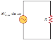
The current in the circuit shown in Figure P32.3 equals 60.0% of the peak current at t = 7.00 ms. What is the lowest source frequency that gives this current?
Figure P32.3 Problems 3 and 5.
Expert Solution & Answer
Want to see the full answer?
Check out a sample textbook solution
Chapter 32 Solutions
Bundle: Physics for Scientists and Engineers, Volume 2, Loose-leaf Version, 10th + WebAssign Printed Access Card for Serway/Jewett's Physics for Scientists and Engineers, 10th, Multi-Term
Ch. 32.2 - Consider the voltage phasor in Figure 32.4, shown...Ch. 32.3 - Consider the AC circuit in Figure 32.8. The...Ch. 32.4 - Consider the AC circuit in Figure 32.11. The...Ch. 32.4 - Consider the AC circuit in Figure 32.12. The...Ch. 32.5 - Label each part of Figure 32.16, (a), (b), and...Ch. 32.6 - An AC source drives an RLC circuit with a fixed...Ch. 32.7 - What is the impedance of a series RLC circuit at...Ch. 32 - (a) What is the resistance of a lightbulb that...Ch. 32 - A certain lightbulb is rated at 60.0 W when...Ch. 32 - The current in the circuit shown in Figure P32.3...
Ch. 32 - Figure P32.4 shows three lightbulbs connected to a...Ch. 32 - In the AC circuit shown in Figure P32.3, R = 70.0 ...Ch. 32 - In a purely inductive AC circuit as shown in...Ch. 32 - Prob. 7PCh. 32 - A 20.0-mH inductor is connected to a North...Ch. 32 - An AC source has an output rms voltage of 78.0 V...Ch. 32 - Review. Determine the maximum magnetic flux...Ch. 32 - A 1.00-mF capacitor is connected to a North...Ch. 32 - An AC source with an output rms voltage of 86.0 V...Ch. 32 - What is the maximum current in a 2.20-F capacitor...Ch. 32 - A capacitor C is connected to a power supply that...Ch. 32 - In addition to phasor diagrams showing voltages...Ch. 32 - An AC source with Vmax = 150 V and f = 50.0 Hz is...Ch. 32 - You are working in a factory and have been tasked...Ch. 32 - Prob. 18PCh. 32 - An RLC circuit consists of a 150- resistor, a...Ch. 32 - A 60.0-ft resistor is connected in series with a...Ch. 32 - A series RLC circuit has a resistance of 45.0 and...Ch. 32 - Prob. 22PCh. 32 - A series RLC circuit has a resistance of 22.0 and...Ch. 32 - An AC voltage of the form v = 90.0 sin 350t, where...Ch. 32 - The LC circuit of a radar transmitter oscillates...Ch. 32 - A series RLC circuit has components with the...Ch. 32 - You wish to build a series RLC circuit for a...Ch. 32 - A 10.0- resistor, 10.0-mH inductor, and 100-F...Ch. 32 - A resistor R, inductor L, and capacitor C are...Ch. 32 - The primary coil of a transformer has N1 = 350...Ch. 32 - A person is working near the secondary of a...Ch. 32 - A transmission line that has a resistance per unit...Ch. 32 - Prob. 33APCh. 32 - A 400- resistor, an inductor, and a capacitor are...Ch. 32 - Energy is to be transmitted over a pair of copper...Ch. 32 - Energy is to be transmitted over a pair of copper...Ch. 32 - A transformer may be used to provide maximum power...Ch. 32 - Show that the rms value for the sawtooth voltage...Ch. 32 - Marie Cornu, a physicist at the Polytechnic...Ch. 32 - A series RLC circuit has resonance angular...Ch. 32 - Review. One insulated conductor from a household...Ch. 32 - (a) Sketch a graph of the phase angle for an RLC...Ch. 32 - Prob. 43APCh. 32 - Review. In the circuit shown in Figure P32.44,...Ch. 32 - You have decided to build your own speaker system...Ch. 32 - A series RLC circuit is operating at 2.00 103 Hz....Ch. 32 - You are trying to become a member of the Physics...Ch. 32 - A series RLC circuit in which R = l.00 , L = 1.00...Ch. 32 - The resistor in Figure P32.49 represents the...Ch. 32 - An 80.0- resistor and a 200-mH inductor are...Ch. 32 - Prob. 51CP
Knowledge Booster


Learn more about
Need a deep-dive on the concept behind this application? Look no further. Learn more about this topic, physics and related others by exploring similar questions and additional content below.Similar questions
- In a purely inductive AC circuit as shown in Figure P32.6, Vmax = 100 V. (a) The maximum current is 7.50 A at 50.0 Hz. Calculate the inductance L. (b) What If? At what angular frequency is the maximum current 2.50 A? Figure P32.6 Problem 6 and 7.arrow_forwardThe RC high-pass filter shown in Figure P33.53 has a resistance R = 0.500 and a capacitance C = 613 F. What is the ratio of the amplitude of the output voltage to that of the input voltage for this filter for a source frequency of 600 Hz?arrow_forwardAn PLC series circuit with R=600 , L = 30 mH. and c=0.050F is driven by an ac source whose frequency and voltage amplitude are 500 Hz and 50 V, respectively, (a) What is the impedance of the circuit? (b) What is the amplitude of the current in the circuit? (c) What is the phase angle between the emf of the source and the current?arrow_forward
- A series RLC circuit has resistance R = 50.0 and inductance L. = 0.500 H. (a) Find the circuits capacitance C if the voltage source operates at a frequency of f = 60.0 Hz and the impedance is Z = R = 50.0 . (b) What is the phase angle between the current and the voltage?arrow_forwardAn inductor and a resistor are connected in series across an AC source as in Figure OQ33.1. Immediately after the switch is closed, which of the following statements is true? (a) The current in the circuit is V/R. (b) The voltage across the inductor is zero, (c) The current in the circuit is zero, (d) The voltage across the resistor is V (e) The voltage across the inductor is half its maximum value.arrow_forwardIn the AC circuit shown in Figure P32.3, R = 70.0 and the output voltage of the AC source is Vmax sin t. (a) If VR = 0.250 Vmax for the first time at t = 0.0100 s, what is the angular frequency of the source? (b) What is the next value of t for which VR = 0.250 Vmax? Figure P32.6 Problem 3 and 5.arrow_forward
- Problems 71 and 72 paired. Figure P33.71 shows a series RLC circuit with a 25.0- resistor, a 430.0-mH inductor, and a 24.0-F capacitor connected to an AC source with Vmax = 60.0 V operating at 60.0 Hz. What is the maximum voltage across the a. resistor, b. inductor, and c. capacitor in the circuit? FIGURE P33.71 Problems 71 and 72.arrow_forwardIn an RLC series circuit, the voltage amplitude and frequency of the source are 100 V and 500 Hz, respectively, an R = 5O0. L=0.20H, and C=2.0F . (a)What is the impedance of the circuit? (b) What is the amplitude of the current from the source? (C) If the emf of the source Is given by v(tt)=(100V)sin , how does the current vary with time? (d) Repeat the calculations with C changed to 0.20F .arrow_forwardA series RLC circuit has resistance R = 50.0 and inductance L. = 0.500 H. (a) Find the circuits capacitance C if the voltage source operates at a frequency of f = 60.0 Hz and the impedance is Z = R = 50.0 . (b) What is the phase angle between the current and the voltage?arrow_forward
- In a purely inductive AC circuit as shown in Figure P21.15, Vmax = 100. V. (a) The maximum current is 7.50 A at 50.0 Hz. Calculate the inductance L. (b) At what angular frequency is the maximum current 2.50A? Figure p21.15arrow_forwardIn the transformer shown in Figure P33.51, the load resistance RL is 50.0 . The turns ratio N1/N2 is 2.50, anti the rms source voltage is Vs = 80.0 V. If a voltmeter across the load resistance measures an rms voltage of 25.0 V, what is the source resistance Rs?arrow_forwardIn the LC circuit in Figure 33.11, the inductance is L = 19.8 mH and the capacitance is C = 19.6 mF. At some moment, UB = UE= 17.5 mJ. a. What is the maximum charge stored by the capacitor? b. What is the maximum current in the circuit? c. At t = 0, the capacitor is fully charged. Write an expression for the charge stored by the capacitor as a function of lime. d. Write an expression for the current as a function of time.arrow_forward
arrow_back_ios
SEE MORE QUESTIONS
arrow_forward_ios
Recommended textbooks for you
 Physics for Scientists and EngineersPhysicsISBN:9781337553278Author:Raymond A. Serway, John W. JewettPublisher:Cengage Learning
 Physics for Scientists and Engineers with Modern ...PhysicsISBN:9781337553292Author:Raymond A. Serway, John W. JewettPublisher:Cengage Learning
 College PhysicsPhysicsISBN:9781305952300Author:Raymond A. Serway, Chris VuillePublisher:Cengage Learning
 College PhysicsPhysicsISBN:9781285737027Author:Raymond A. Serway, Chris VuillePublisher:Cengage Learning
 Physics for Scientists and Engineers: Foundations...PhysicsISBN:9781133939146Author:Katz, Debora M.Publisher:Cengage Learning
Physics for Scientists and Engineers
Physics
ISBN:9781337553278
Author:Raymond A. Serway, John W. Jewett
Publisher:Cengage Learning
Physics for Scientists and Engineers with Modern ...
Physics
ISBN:9781337553292
Author:Raymond A. Serway, John W. Jewett
Publisher:Cengage Learning
College Physics
Physics
ISBN:9781305952300
Author:Raymond A. Serway, Chris Vuille
Publisher:Cengage Learning
College Physics
Physics
ISBN:9781285737027
Author:Raymond A. Serway, Chris Vuille
Publisher:Cengage Learning
Physics for Scientists and Engineers: Foundations...
Physics
ISBN:9781133939146
Author:Katz, Debora M.
Publisher:Cengage Learning
Introduction To Alternating Current; Author: Tutorials Point (India) Ltd;https://www.youtube.com/watch?v=0m142qAZZpE;License: Standard YouTube License, CC-BY