Videos
(a)
The maximum voltage between points
(a)
Answer to Problem 24P
The maximum voltage between points
Explanation of Solution
Consider the phasor diagram as shown in the figure 1.
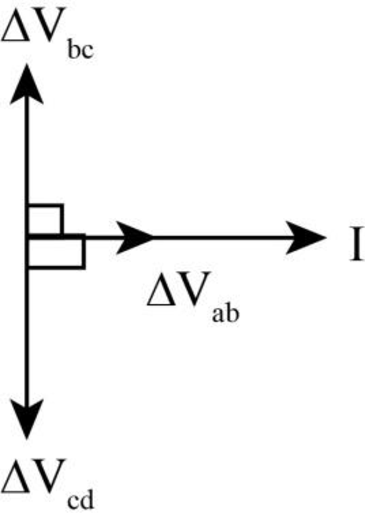
Figure (1)
Write the expression for the maximum current in the circuit.
Here,
Write the expression for the maximum voltage between points
Here,
Conclusion:
Substitute
Substitute
Therefore, the maximum voltage between points
(b)
The maximum voltage between points
(b)
Answer to Problem 24P
The maximum voltage between points
Explanation of Solution
Write the expression for the maximum voltage between points
Here,
Conclusion:
Substitute
Therefore, the maximum voltage between points
(c)
The maximum voltage between points
(c)
Answer to Problem 24P
The maximum voltage between points
Explanation of Solution
Write the expression for the maximum voltage between points
Here,
Conclusion:
Substitute
Therefore, the maximum voltage between points
(d)
The maximum voltage between points
(d)
Answer to Problem 24P
The maximum voltage between points
Explanation of Solution
Write the expression for the maximum voltage between points
Here,
Conclusion:
Substitute
Therefore, the maximum voltage between points
Want to see more full solutions like this?
Chapter 33 Solutions
Physics for Scientists and Engineers with Modern Physics Technology Update


- In the AC circuit shown in Figure P32.3, R = 70.0 and the output voltage of the AC source is Vmax sin t. (a) If VR = 0.250 Vmax for the first time at t = 0.0100 s, what is the angular frequency of the source? (b) What is the next value of t for which VR = 0.250 Vmax? Figure P32.6 Problem 3 and 5.arrow_forwardIn a purely inductive AC circuit as shown in Figure P21.15, Vmax = 100. V. (a) The maximum current is 7.50 A at 50.0 Hz. Calculate the inductance L. (b) At what angular frequency is the maximum current 2.50A? Figure p21.15arrow_forwardThe RC high-pass filter shown in Figure P33.53 has a resistance R = 0.500 and a capacitance C = 613 F. What is the ratio of the amplitude of the output voltage to that of the input voltage for this filter for a source frequency of 600 Hz?arrow_forward
- An inductor and a resistor are connected in series across an AC source as in Figure OQ33.1. Immediately after the switch is closed, which of the following statements is true? (a) The current in the circuit is V/R. (b) The voltage across the inductor is zero, (c) The current in the circuit is zero, (d) The voltage across the resistor is V (e) The voltage across the inductor is half its maximum value.arrow_forwardIn a purely inductive AC circuit as shown in Figure P21.15, Vmax = 100. V. (a) The maximum current is 7.50 A at 50.0 Hz. Calculate the inductance L. (b) At what angular frequency is the maximum current 2.50A? Figure p21.15arrow_forwardThe emf of an ac source is given by v(t)=V0sint, where V0=100V and =200 . Find an expression that represents the output current of the source if it is connected across (a) a 20-pF capacitor, (b) a 20-mH inductor, and (c) a 50 resistor.arrow_forward
- An PLC series circuit with R=600 , L = 30 mH. and c=0.050F is driven by an ac source whose frequency and voltage amplitude are 500 Hz and 50 V, respectively, (a) What is the impedance of the circuit? (b) What is the amplitude of the current in the circuit? (c) What is the phase angle between the emf of the source and the current?arrow_forwardVP31.3.3 An ac circuit includes a 155 Ω resistor in series with an 8.00 μF capacitor. The current in the circuit has amplitude 4.00×10⁻³ A. (a) Find the frequency for which the capacitive reactance equals the resistance. (b) At this frequency, what are the amplitudes of the voltages across the resistor and capacitor?arrow_forwardA capacitor is connected to an ac generator that has a frequency of 3.4 kHz and produces a voltage of 2.0 V. The current in the capacitor is 35 mA. When the same capacitor is connected to a second ac generator that has a frequency of 5.0 kHz, the current in the capacitor is 85 mA. What voltage does the second generator produce?arrow_forward
- An AC source with a maximum voltage of 150. V and f =50.0 Hz is connected between points a and d in Figure P21.29.Calculate the rms voltages between points (a) a and b, (b) band c, (c) c and d, and (d) b and d.arrow_forwardAn AC source operating at 60. Hz with a maximum voltage of170 V is connected in series with a resistor (R = 1.2 kΩ) anda capacitor (C 5 2.5 µF). (a) What is the maximum value ofthe current in the circuit? (b) What are the maximum valuesof the potential difference across the resistor and the capacitor?(c) When the current is zero, what are the magnitudesof the potential difference across the resistor, the capacitor,and the AC source? How much charge is on the capacitor atthis instant? (d) When the current is at a maximum, what arethe magnitudes of the potential differences across the resistor,the capacitor, and the AC source? How much charge is on thecapacitor at this instant?arrow_forwardAn ac generator whose emf is given by v(t) = (4.00 V) sin (1.00 ×10⁴ rad/s)t) is connected to an RLC circuit for which L = 2.00 × 10⁻³ H , C = 4.00 × 10⁻⁶ F , and R = 5.00 Ω . (a) What is the rms voltage across the generator? (b) What is the impedance of the circuit? (c) What is the average power output of the generator?arrow_forward
 Physics for Scientists and EngineersPhysicsISBN:9781337553278Author:Raymond A. Serway, John W. JewettPublisher:Cengage Learning
 Physics for Scientists and Engineers with Modern ...PhysicsISBN:9781337553292Author:Raymond A. Serway, John W. JewettPublisher:Cengage Learning
 College PhysicsPhysicsISBN:9781285737027Author:Raymond A. Serway, Chris VuillePublisher:Cengage Learning
 College PhysicsPhysicsISBN:9781305952300Author:Raymond A. Serway, Chris VuillePublisher:Cengage Learning
 Physics for Scientists and Engineers, Technology ...PhysicsISBN:9781305116399Author:Raymond A. Serway, John W. JewettPublisher:Cengage Learning