Videos
(a)
The moment of the couple (M) formed by two forces by resolving each force into horizontal and vertical components and adding the moments of the two resulting couples.
(a)
Answer to Problem 3.71P
The moment of the couple (M) formed by two forces by resolving each force into horizontal and vertical components and adding the moments of the two resulting couples is
Explanation of Solution
Given information:
The applied force at point B
The applied force at point C
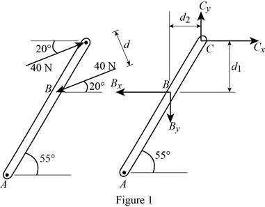
The length of AB (x) is 390 mm.
The length of BC (y) is 270 mm.
The angle of the inclined lever
The angle of the force acting at point C
Calculation:
Draw the free body diagram of the lever as in Figure (1).
Calculate the vertical height of BC
Substitute 270 mm for y and
Calculate the horizontal height of BC
Substitute 270 mm for y and
Calculate the horizontal reaction at C
Substitute 40 N for
Calculate the vertical reaction at C
Substitute 40 N for
Find the moment of the couple (M):
Take the moment about B.
Substitute 0.22117 m for
Thus, the moment of the couple (M) formed by two forces by resolving each force into horizontal and vertical components and adding the moments of the two resulting couples is
(b)
The moment of the couple (M) formed by two forces by using the perpendicular distance between the two forces.
(b)
Answer to Problem 3.71P
The moment of the couple (M) formed by two forces by using the perpendicular distance between the two forces is
Explanation of Solution
Given information:
The applied force at point B
The applied force at point C
The length of AB (x) is 390 mm.
The length of BC (y) is 270 mm.
The angle of the inclined lever
The angle of the force acting at point C
Calculation:
Calculate the distance (d) between the two forces using the relation:
Substitute 270 mm for y,
Calculate the moment of the couple (M) formed by two forces by using the perpendicular distance between the two forces using the relation:
Substitute 40 N for F and 0.154866 m for d.
Thus, the moment of the couple (M) formed by two forces by using the perpendicular distance between the two forces is
(c)
The moment of the couple (M) formed by summing the moments of two forces about point A.
(c)
Answer to Problem 3.71P
The moment of the couple (M) formed by summing the moments of two forces about point A is
Explanation of Solution
Given information:
The applied force at point B
The applied force at point C
The length of AB (x) is 390 mm.
The length of BC (y) is 270 mm.
The angle of the inclined lever
The angle of the force acting at point C
Calculation:
Calculate the position vector of from point B to point A
Substitute 390 mm for x and
Calculate the force at B by resolving in horizontal and vertical direction using the relation:
Substitute 40 N for
Calculate the position vector of from point C to point A
Substitute 390 mm for x, 270 mm for y and
Calculate the force at C by resolving in horizontal and vertical direction using the relation:
Substitute 40 N for
Calculate the moment of the couple (M) formed by summing the moments of two forces about point A using the relation:
Take the moment about A.
Substitute
Thus, the moment of the couple (M) formed by summing the moments of two forces about point A is
Want to see more full solutions like this?
Chapter 3 Solutions
Connect 2 Semester Access Card for Vector Mechanics for Engineers: Statics and Dynamics


 Elements Of ElectromagneticsMechanical EngineeringISBN:9780190698614Author:Sadiku, Matthew N. O.Publisher:Oxford University Press
 Mechanics of Materials (10th Edition)Mechanical EngineeringISBN:9780134319650Author:Russell C. HibbelerPublisher:PEARSON
 Thermodynamics: An Engineering ApproachMechanical EngineeringISBN:9781259822674Author:Yunus A. Cengel Dr., Michael A. BolesPublisher:McGraw-Hill Education
 Control Systems EngineeringMechanical EngineeringISBN:9781118170519Author:Norman S. NisePublisher:WILEY
 Mechanics of Materials (MindTap Course List)Mechanical EngineeringISBN:9781337093347Author:Barry J. Goodno, James M. GerePublisher:Cengage Learning
 Engineering Mechanics: StaticsMechanical EngineeringISBN:9781118807330Author:James L. Meriam, L. G. Kraige, J. N. BoltonPublisher:WILEY