Vector Mechanics for Engineers: Statics, 11th Edition
11th Edition
ISBN: 9780077687304
Author: Ferdinand P. Beer, E. Russell Johnston Jr., David Mazurek
Publisher: McGraw-Hill Education
bartleby

Videos

Question
Book Icon
Chapter 3.3, Problem 3.79P
To determine

Find the magnitude of the couple (M) and direction of its axis after replacing two couples in to single equivalent couple.

Expert Solution & Answer
Check Mark

Answer to Problem 3.79P

The magnitude of the couple (M) and direction of its axis (θx,θy,θz) are 2.72Nm_ and 134.9°,58°,61.9°_ respectively.

Explanation of Solution

Given information:

The two vertical forces (M3) is 10 N.

The inclined force acting at point B (FB) is 50 N.

The inclined force acting at point C (FC) is 50 N.

The force acting at the point E (FE) is 12.5 N.

The force acting at the point D (FD) is 12.5 N.

The height between point C and F (CF) is 120 mm.

The height between point F and A (FA) is 120 mm.

The horizontal distance between point E and  D (ED) is 192 mm.

The height between point E and B (EB) is 144 mm.

The distance between point C and D (CD) is 160 mm.

Calculation:

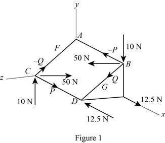
Replace the couple in the ABCD plane with two couple’s P and Q.

Show the couple ABCD by replacing with two couple’s P and Q as Figure 1.

<x-custom-btb-me data-me-id='1725' class='microExplainerHighlight'>Vector</x-custom-btb-me> Mechanics for Engineers: Statics, 11th Edition, Chapter 3.3, Problem 3.79P

Calculate the distance CG using the formula:

Use Pythagoras theorem,

CG=CD2+CF2

Substitute 160 mm for CD and 120 mm for CF.

CG=(160)2+(120)2=200mm

Calculate the force (P) acting at the point B using the formula:

P=FBCDCG

Substitute 50 N for FB, 160 mm for CD and 200 mm for CG.

P=50(160200)=40N

Calculate the force (Q) acting at the point C using the formula:

Q=FCCFCG

Substitute 50 N for FC, 120 mm for CF and 200 mm for CG.

Q=50(120200)=30N

Calculate the angle (θ) using the relation:

tanθ=EBED

Substitute 144 mm for EB and 192 mm for ED.

tanθ=144192θ=tan1(0.75)=36.87°

Calculate the couple vector (M1) perpendicular to plane ABCD using the relation:

M1=[P×(CF+FA)][Q(CD)]

Substitute 40 N for P, 120 mm for CF, 120 mm for FA, 30 N for Q, 160 mm for CD.

M1=[40×(120+120)][30(160)]=4800Nmm×11000mmm=4.80Nm

Write the couple vector (M1) perpendicular to plane ABCD in vector form:

M1=(M1cosθ)j+(M1sinθ)k

Substitute 4.80Nm for M1 and 36.87° for θ.

M1=(4.80cos36.87)j+(4.80sin36.87)k=3.84j+2.88k

Calculate the couple vector (M2) in the xy plane using the relation:

M2=FD×ED

Substitute 12.5 N for FD and 192 mm for ED.

M2=12.5×(192mm×11000mmm)=2.4Nm

Write the couple vector (M2) in the xy plane in vector form:

M2=(2.4Nm)j

Calculate the position vector of BC (rB/C) using the relation:

rB/C=CDi+EBjEDk

Substitute 160 mm for CD, 144 mm for EB and 192 mm for ED.

rB/C=(160mm×11000mmm)i+(144mm×11000mmm)j(192mm×11000mmm)k=0.16i+0.144j0.192k

Calculate the couple vector (M3) using the relation:

(M3)=rB/C×M3

Substitute 0.16i+0.144j0.192k for rB/C and (10N)j for M3.

(M3)=0.16i+0.144j0.192k×(10)j=1.6k1.92i

Calculate magnitude of the couple (M) using the relation:

M=M1+M2+M3

Substitute 3.84j+2.88k for M1, (2.4Nm)j for M2 and 1.6k1.92i for M3.

M=3.84j+2.88k2.4j1.6k1.92i=1.92i+1.44j+1.28kM=(1.92)2+(1.44)2+(1.28)2=2.72Nm

Calculate the direction of axis along x direction (θx) by considering the i component using the relation:

cosθx=M(i)M

Substitute 1.92Nm for M(i) and 2.72Nm for M.

cosθx=1.922.72=cos1(1.922.72)=134.9°

Calculate the direction of axis along y direction (θy) by considering the j component using the relation:

cosθy=M(j)M

Substitute 1.44Nm for M(j) and 2.72Nm for M.

cosθy=1.442.72=cos1(1.442.72)=58.0°

Calculate the direction of axis along z direction (θz) by considering the k component using the relation:

cosθz=M(k)M

Substitute 1.28Nm for M(k) and 2.72Nm for M.

cosθz=1.282.72=cos1(1.282.72)=61.9°

Therefore, the magnitude of the couple (M) and direction of its axis (θx,θy,θz) are 2.72Nm_ and 134.9°,58°,61.9°_ respectively.

Want to see more full solutions like this?

Subscribe now to access step-by-step solutions to millions of textbook problems written by subject matter experts!

Chapter 3 Solutions

Vector Mechanics for Engineers: Statics, 11th Edition

Ch. 3.1 - 3.11 and 3.12The tailgate of a car is supported by...Ch. 3.1 - 3.11 and 3.12The tailgate of a car is supported by...Ch. 3.1 - 3.13 and 3.14It is known that the connecting rod...Ch. 3.1 - 3.13 and 3.14It is known that the connecting rod...Ch. 3.1 - 3.15 Form the vector products B × C and B′ × C,...Ch. 3.1 - Prob. 3.16PCh. 3.1 - 3.17 A plane contains the vectors A and B....Ch. 3.1 - Prob. 3.18PCh. 3.1 - Prob. 3.19PCh. 3.1 - 3.20 Determine the moment about the origin O of...Ch. 3.1 - Before the trunk of a large tree is felled, cables...Ch. 3.1 - The 12-ft boom AB has a fixed end A. A steel cable...Ch. 3.1 - A 200-N force is applied as shown to the bracket...Ch. 3.1 - Prob. 3.24PCh. 3.1 - A 6-ft-long fishing rod AB is securely anchored in...Ch. 3.1 - A precast concrete wall section is temporarily...Ch. 3.1 - In Prob. 3.22, determine the perpendicular...Ch. 3.1 - Prob. 3.28PCh. 3.1 - Prob. 3.29PCh. 3.1 - In Prob. 3.25, determine the perpendicular...Ch. 3.1 - In Prob. 3.25, determine the perpendicular...Ch. 3.1 - In Prob. 3.26, determine the perpendicular...Ch. 3.1 - In Prob. 3.26, determine the perpendicular...Ch. 3.1 - Determine the value of a that minimizes the...Ch. 3.2 - 3.35 Given the vectors P = 2i + 3j − k, Q = 5i −...Ch. 3.2 - Form the scalar product B C and use the result...Ch. 3.2 - Prob. 3.37PCh. 3.2 - Prob. 3.38PCh. 3.2 - Knowing that the tension in cable AC is 280 lb,...Ch. 3.2 - Knowing that the tension in cable AD is 180 lb,...Ch. 3.2 - Ropes AB and BC are two of the ropes used to...Ch. 3.2 - Ropes AB and BC are two of the ropes used to...Ch. 3.2 - The 20-in. tube AB can slide along a horizontal...Ch. 3.2 - Solve Prob. 3.43 for the position corresponding to...Ch. 3.2 - Prob. 3.45PCh. 3.2 - Prob. 3.46PCh. 3.2 - A crane is oriented so that the end of the 25-m...Ch. 3.2 - 3.48The 25-m crane boom AO lies in the yz plane....Ch. 3.2 - To loosen a frozen valve, a force F with a...Ch. 3.2 - 3.50When a force F is applied to the handle of the...Ch. 3.2 - 3.51 To lift a heavy crate, a man uses a block and...Ch. 3.2 - Prob. 3.52PCh. 3.2 - A farmer uses cables and winch pullers B and E to...Ch. 3.2 - Solve Prob. 3.53 when the tension in cable AB is...Ch. 3.2 - Prob. 3.55PCh. 3.2 - Prob. 3.56PCh. 3.2 - The frame ACD is hinged at A and D and is...Ch. 3.2 - In Prob. 3.57, determine the moment about the...Ch. 3.2 - The triangular plate ABC is supported by...Ch. 3.2 - 3.60The triangular plate ABC is supported by...Ch. 3.2 - Prob. 3.61PCh. 3.2 - Prob. 3.62PCh. 3.2 - Two forces F1 and F2 in space have the same...Ch. 3.2 - Prob. 3.64PCh. 3.2 - Prob. 3.65PCh. 3.2 - In Prob. 3.57, determine the perpendicular...Ch. 3.2 - In Prob. 3.58, determine the perpendicular...Ch. 3.2 - In Prob. 3.59, determine the perpendicular...Ch. 3.2 - In Prob. 3.60, determine the perpendicular...Ch. 3.3 - Two 80-N forces are applied as shown to the...Ch. 3.3 - Prob. 3.71PCh. 3.3 - 3.72 Four pegs are attached to a board as shown....Ch. 3.3 - Four pegs of the same diameter are attached to a...Ch. 3.3 - A piece of plywood in which several holes are...Ch. 3.3 - Prob. 3.75PCh. 3.3 - Prob. 3.76PCh. 3.3 - 3.77If P = 20 lb in the figure, replace the three...Ch. 3.3 - 3.78 Replace the two couples shown with a single...Ch. 3.3 - Prob. 3.79PCh. 3.3 - Shafts A and B connect the gear box to the wheel...Ch. 3.3 - A 500-N force is applied to a bent plate as shown....Ch. 3.3 - Prob. 3.82PCh. 3.3 - A dirigible is tethered by a cable attached to its...Ch. 3.3 - A 30-lb vertical force P is applied at A to the...Ch. 3.3 - A worker tries to move a rock by applying a 360-N...Ch. 3.3 - A worker tries to move a rock by applying a 360-N...Ch. 3.3 - The shearing forces exerted on the cross section...Ch. 3.3 - Prob. 3.88PCh. 3.3 - Three control rods attached to a lever ABC exert...Ch. 3.3 - A rectangular plate is acted upon by the force and...Ch. 3.3 - While tapping a hole, a machinist applies the...Ch. 3.3 - A hexagonal plate is acted upon by the force P and...Ch. 3.3 - Replace the 250-kN force P with an equivalent...Ch. 3.3 - A 2.6-kip force is applied at point D of the...Ch. 3.3 - Replace the 150-N force with an equivalent...Ch. 3.3 - To keep a door closed, a wooden stick is wedged...Ch. 3.3 - A 46-lb force F and a 2120-lbin. couple M are...Ch. 3.3 - A 110-N force acting in a vertical plane parallel...Ch. 3.3 - Prob. 3.99PCh. 3.3 - Prob. 3.100PCh. 3.4 - Prob. 3.101PCh. 3.4 - Prob. 3.102PCh. 3.4 - Prob. 3.103PCh. 3.4 - Five separate force-couple systems act at the...Ch. 3.4 - The weights of two children sitting at ends A and...Ch. 3.4 - Three stage lights are mounted on a pipe as shown....Ch. 3.4 - A beam supports three loads of given magnitude and...Ch. 3.4 - A 6 12-in. plate is subjected to four loads as...Ch. 3.4 - Prob. 3.109PCh. 3.4 - To test the strength of a 625 500-mm suitcase,...Ch. 3.4 - Prob. 3.111PCh. 3.4 - Pulleys A and B are mounted on bracket CDEF. The...Ch. 3.4 - 3.113 A truss supports the loading shown....Ch. 3.4 - A couple of magnitude M = 80 lbin. and the three...Ch. 3.4 - A couple M and the three forces shown are applied...Ch. 3.4 - A machine component is subjected to the forces and...Ch. 3.4 - Solve Prob. 3.116, assuming that P = 60 N.Ch. 3.4 - As follower AB rolls along the surface of member...Ch. 3.4 - A machine component is subjected to the forces...Ch. 3.4 - Two 150-mm-diameter pulleys are mounted on line...Ch. 3.4 - As an adjustable brace BC is used to bring a wall...Ch. 3.4 - In order to unscrew the tapped faucet A, a plumber...Ch. 3.4 - Assuming = 60 in Prob. 3.122, replace the two...Ch. 3.4 - Four forces are applied to the machine component...Ch. 3.4 - A blade held in a brace is used to tighten a screw...Ch. 3.4 - A mechanic uses a crowfoot wrench to loosen a bolt...Ch. 3.4 - Prob. 3.127PCh. 3.4 - Prob. 3.128PCh. 3.4 - Four signs are mounted on a frame spanning a...Ch. 3.4 - Prob. 3.130PCh. 3.4 - A concrete foundation mat of 5-m radius supports...Ch. 3.4 - Determine the magnitude and the point of...Ch. 3.4 - Prob. 3.133PCh. 3.4 - A piece of sheet metal is bent into the shape...Ch. 3.4 - Prob. 3.135PCh. 3.4 - Prob. 3.136PCh. 3.4 - Two bolts at A and B are tightened by applying the...Ch. 3.4 - Two bolts at A and B are tightened by applying the...Ch. 3.4 - Prob. 3.139PCh. 3.4 - A flagpole is guyed by three cables. If the...Ch. 3.4 - 3.141 and 3.142Determine whether the...Ch. 3.4 - 3.141 and 3.142Determine whether the...Ch. 3.4 - Replace the wrench shown with an equivalent system...Ch. 3.4 - Show that, in general, a wrench can be replaced...Ch. 3.4 - Show that a wrench can be replaced with two...Ch. 3.4 - Show that a wrench can be replaced with two...Ch. 3 - A 300-N force P is applied at point A of the bell...Ch. 3 - A winch puller AB is used to straighten a fence...Ch. 3 - A small boat hangs from two davits, one of which...Ch. 3 - Prob. 3.150RPCh. 3 - A single force P acts at C in a direction...Ch. 3 - 3.152 A small boat hangs from two davits, one of...Ch. 3 - In a manufacturing operation, three holes are...Ch. 3 - A 260-lb force is applied at A to the rolled-steel...Ch. 3 - Prob. 3.155RPCh. 3 - A 77-N force F1 and a 31-Nm couple M1 are applied...Ch. 3 - Three horizontal forces are applied as shown to a...Ch. 3 - While using a pencil sharpener, a student applies...
Knowledge Booster
Background pattern image
Mechanical Engineering
Learn more about
Need a deep-dive on the concept behind this application? Look no further. Learn more about this topic, mechanical-engineering and related others by exploring similar questions and additional content below.
Recommended textbooks for you
Text book image
Elements Of Electromagnetics
Mechanical Engineering
ISBN:9780190698614
Author:Sadiku, Matthew N. O.
Publisher:Oxford University Press
Text book image
Mechanics of Materials (10th Edition)
Mechanical Engineering
ISBN:9780134319650
Author:Russell C. Hibbeler
Publisher:PEARSON
Text book image
Thermodynamics: An Engineering Approach
Mechanical Engineering
ISBN:9781259822674
Author:Yunus A. Cengel Dr., Michael A. Boles
Publisher:McGraw-Hill Education
Text book image
Control Systems Engineering
Mechanical Engineering
ISBN:9781118170519
Author:Norman S. Nise
Publisher:WILEY
Text book image
Mechanics of Materials (MindTap Course List)
Mechanical Engineering
ISBN:9781337093347
Author:Barry J. Goodno, James M. Gere
Publisher:Cengage Learning
Text book image
Engineering Mechanics: Statics
Mechanical Engineering
ISBN:9781118807330
Author:James L. Meriam, L. G. Kraige, J. N. Bolton
Publisher:WILEY
Physics 33 - Fluid Statics (1 of 10) Pressure in a Fluid; Author: Michel van Biezen;https://www.youtube.com/watch?v=mzjlAla3H1Q;License: Standard YouTube License, CC-BY