
MECHANICS OF MATERIALS (LL) & ACCESS CA
7th Edition
ISBN: 9781260435306
Author: BEER
Publisher: MCG
expand_more
expand_more
format_list_bulleted
Concept explainers
Videos
Textbook Question
Chapter 3.3, Problem 50P
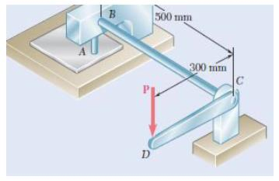
A hole is punched at A in a plastic sheet by applying a 600-N force P to end D of lever CD, which is rigidly attached to the solid cylindrical shaft BC. Design specifications require that the displacement of D should not exceed 15 mm from the time the punch first touches the plastic sheet to the time it actually penetrates it. Determine the required diameter of shaft BC if the shaft is made of a steel with G = 77.2 GPa and τall = 80 MPa.
Expert Solution & Answer
Want to see the full answer?
Check out a sample textbook solution
Students have asked these similar questions
1. A steel shaft is to be manufactured either as a solid circular or as circular tube. The shaft is required to transmit a torque of 1200 Nm without exceeding an allowable shear stress of 40 MPa, nor an allowable rate of twist of 0.75º/m. For G = 78GPa, determine:
a. The required diameter do of the solid shaft.b. The required outer diameter d2 of the hollow shaft if the thickness t of the shaft is specified as one-tenth of the outer diameter.c. The ratio of diameters (that is, the ratio d2/do and the ratio of the weights of the hollow and solid shafts.
Gears b and c have diameters of 10 cm and 4 cm, respectively. The maximum shear stress supported by the bars is 550 kgf/cm^2 and the material from which they are manufactured has a shear modulus G = 8x10^5 kgf/cm^2.
Determine:
The diameter of each bar, such that the maximum shear stress is not exceeded.
The torsional rotation of point d.
T = 12 Ton-m
A hollow steel shaft of length 1.75 m transmits 2000 kW of power at a speed of150 rev/min. The inside diameter is to be 0.75 times the outside diameter. Themaximum allowable torsional shear stress for the steel is 130 MN/m2and themodulus of rigidity (G) for the steel is 83 GN/m2. Given that a factor of safety of2 is required for the shaft, determine:i) the torque acting on the shaft;ii) the required external and internal diameters for the shaft;
iii) the torsional shear stress set-up in the shaft material at the inside surfaceof the hollow shaft, and sketch the stress distribution through the shaftwall;iv) the angle of twist (in degrees) due to the torque.
Chapter 3 Solutions
MECHANICS OF MATERIALS (LL) & ACCESS CA
Ch. 3.1 - Determine the torque T that causes a maximum...Ch. 3.1 - For the cylindrical shaft shown, determine the...Ch. 3.1 - (a) Determine the torque T that causes a maximum...Ch. 3.1 - (a) Determine the maximum shearing stress caused...Ch. 3.1 - (a) For the 3-in.-diameter solid cylinder and...Ch. 3.1 - Fig. P3.6 3.6 A torque T=3 kN m is applied to the...Ch. 3.1 - The solid spindle AB is made of a steel with an...Ch. 3.1 - The solid spindle AB has a diameter ds = 1.5 in....Ch. 3.1 - Fig. P3.9 and P3.10 3.10 The shafts of the pulley...Ch. 3.1 - Knowing that each of the shafts AB, BC, and CD...
Ch. 3.1 - Fig. P3.11 and P3.12 3.12 Knowing that an...Ch. 3.1 - Under normal operating conditions, the electric...Ch. 3.1 - In order to reduce the total mass of the assembly...Ch. 3.1 - The allowable shearing stress is 15 ksi in the...Ch. 3.1 - The allowable shearing stress is 15 ksi in the...Ch. 3.1 - The solid shaft shown is formed of a brass for...Ch. 3.1 - Solve Prob. 3.17 assuming that the direction of Tc...Ch. 3.1 - The solid rod AB has a diameter dAB= 60 mm and is...Ch. 3.1 - Fig. P3.19 and P3.20 3.20 The solid rod AB has a...Ch. 3.1 - A torque of magnitude T = 1000 N m is applied at D...Ch. 3.1 - Fig. P3.21 and P3.22 3.22 A torque of magnitude T...Ch. 3.1 - Under normal operating conditions a motor exerts a...Ch. 3.1 - Fig P3.23 and P3.24 3.24 Under normal operating...Ch. 3.1 - Prob. 25PCh. 3.1 - Fig. P3.25 and P3.26 3.26 The two solid shafts are...Ch. 3.1 - For the gear train shown, the diameters of the...Ch. 3.1 - Fig. P3.27 and P3.28 3.28 A torque T = 900 N m is...Ch. 3.1 - Fig. P3.29 3.29 While the exact distribution of...Ch. 3.1 - Fig. P3.30 3.30 (a) For a given allowable shearing...Ch. 3.3 - Determine the largest allowable diameter of a...Ch. 3.3 - The ship at A has just started to drill for oil on...Ch. 3.3 - (a) For the solid steel shaft shown, determine the...Ch. 3.3 - (a) For the aluminum pipe shown (G = 27 GPa),...Ch. 3.3 - The electric motor exerts a 500 N m-torque on the...Ch. 3.3 - The torques shown are exerted on pulleys and B....Ch. 3.3 - The aluminum rod BC (G = 26 GPa) is bonded to the...Ch. 3.3 - The aluminum rod AB (G = 27 GPa) is bonded to the...Ch. 3.3 - The solid spindle AB has a diameter ds = 1.75 in....Ch. 3.3 - Fig. p3.39 and p3.40 3.40 The solid spindle AB has...Ch. 3.3 - Two shafts, each of 78in. diameter, are connected...Ch. 3.3 - Two solid steel shafts each of 30-mm diameter, are...Ch. 3.3 - A coder F, used to record in digital form the...Ch. 3.3 - Fig. p3.43 3.44 For the gear train described in...Ch. 3.3 - The design specifications of a 1.2-m-long solid...Ch. 3.3 - 3.46 and 3.47 The solid cylindrical rod BC of...Ch. 3.3 - 3.46 and 3.47 The solid cylindrical rod BC of...Ch. 3.3 - The design of the gear-and-shaft system shown...Ch. 3.3 - The electric motor exerts a torque of 900 Nm on...Ch. 3.3 - A hole is punched at A in a plastic sheet by...Ch. 3.3 - The solid cylinders AB and BC are bonded together...Ch. 3.3 - Solve Prob. 3.51, assuming that cylinder AB is...Ch. 3.3 - The composite shaft shown consists of a...Ch. 3.3 - Fig. p3.53 and p3.54 3.54 The composite shaft...Ch. 3.3 - Two solid steel shafts (G = 77.2 GPa) are...Ch. 3.3 - Solve Prob. 3.55, assuming that the shaft AB is...Ch. 3.3 - 3.57 and 3.58 Two solid steel shafts are fitted...Ch. 3.3 - 3.57 and 3.58 Two solid steel shafts are fitted...Ch. 3.3 - The steel jacket CD has been attached to the...Ch. 3.3 - A torque T is applied as shown to a solid tapered...Ch. 3.3 - Prob. 61PCh. 3.3 - A solid shaft and a hollow shaft are made of the...Ch. 3.3 - An annular plate of thickness t and modulus G is...Ch. 3.5 - Determine the maximum shearing stress in a solid...Ch. 3.5 - Determine the maximum shearing stress in a solid...Ch. 3.5 - Using an allowable shearing stress of 4.5 ksi,...Ch. 3.5 - Using an allowable shearing stress of 50 MPa,...Ch. 3.5 - While a steel shaft of the cross section shown...Ch. 3.5 - Determine the required thickness of the 50-mm...Ch. 3.5 - A steel drive shaft is 6 ft long and its outer and...Ch. 3.5 - The hollow steel shaft shown (G = 77.2 GPa, all =...Ch. 3.5 - A steel pipe of 3.5-in. outer diameter is to be...Ch. 3.5 - 3.73 The design of a machine element calls for a...Ch. 3.5 - Three shafts and four gears are used to form a...Ch. 3.5 - Three shafts and four gears are used to form a...Ch. 3.5 - The two solid shafts and gears shown are used to...Ch. 3.5 - Fig. P3.76 and P3.77 3.77 The two solid shafts and...Ch. 3.5 - The shaft-disk-belt arrangement shown is used to...Ch. 3.5 - A 5-ft-long solid steel shaft of 0.875-in....Ch. 3.5 - A 2.5-m-long steel shaft of 30-mm diameter rotates...Ch. 3.5 - The design specifications of a 1.2-m-long solid...Ch. 3.5 - A 1.5-m-long tubular steel shaft (G = 77.2 GPa) of...Ch. 3.5 - Fig. P3.82 and P3.83 3.83 A 1.5-m-long tubular...Ch. 3.5 - The stepped shaft shown must transmit 40 kW at a...Ch. 3.5 - The stepped shaft shown rotates at 450 rpm....Ch. 3.5 - Knowing that the stepped shaft shown transmits a...Ch. 3.5 - The stepped shaft shown must rotate at a frequency...Ch. 3.5 - Fig. P3.87 and P3.88 3.88 The stepped shaft shown...Ch. 3.5 - A torque of magnitude T = 200 lbin. is applied to...Ch. 3.5 - Fig. P3.89, P3.90 and P3.91 3.90 In the stepped...Ch. 3.5 - In the stepped shaft shown, which has a full...Ch. 3.8 - The solid circular shaft shown is made of a steel...Ch. 3.8 - Prob. 93PCh. 3.8 - Prob. 94PCh. 3.8 - Prob. 95PCh. 3.8 - Fig. P3.95 and P3.96 3.96 The solid shaft shown is...Ch. 3.8 - It is observed that a straightened paper clip can...Ch. 3.8 - The solid shaft shown is made of a mild steel that...Ch. 3.8 - Prob. 99PCh. 3.8 - Prob. 100PCh. 3.8 - Prob. 101PCh. 3.8 - Prob. 102PCh. 3.8 - Prob. 103PCh. 3.8 - Prob. 104PCh. 3.8 - A solid circular rod is made of a material that is...Ch. 3.8 - Prob. 106PCh. 3.8 - Prob. 107PCh. 3.8 - Prob. 108PCh. 3.8 - Prob. 109PCh. 3.8 - Prob. 110PCh. 3.8 - Prob. 111PCh. 3.8 - A 50-mm diameter cylinder is made of a brass for...Ch. 3.8 - Prob. 113PCh. 3.8 - The solid circular drill rod AB is made of a steel...Ch. 3.8 - Prob. 115PCh. 3.8 - Prob. 116PCh. 3.8 - After the solid shaft of Prob. 3.116 has been...Ch. 3.8 - The hollow shaft shown is made of a steel that is...Ch. 3.8 - Prob. 119PCh. 3.8 - Prob. 120PCh. 3.10 - Determine the smallest allowable square cross...Ch. 3.10 - Prob. 122PCh. 3.10 - Using all = 70 MPa and G = 27 GPa, determine for...Ch. 3.10 - Prob. 124PCh. 3.10 - Determine the largest torque T that can be applied...Ch. 3.10 - Each of the two brass bars shown is subjected to a...Ch. 3.10 - Prob. 127PCh. 3.10 - Prob. 128PCh. 3.10 - Prob. 129PCh. 3.10 - Shafts A and B are made of the same material and...Ch. 3.10 - Prob. 131PCh. 3.10 - Shafts A and B are made of the same material and...Ch. 3.10 - Prob. 133PCh. 3.10 - Prob. 134PCh. 3.10 - Prob. 135PCh. 3.10 - A 36-kipin. torque is applied to a 10-ft-long...Ch. 3.10 - A 4-m-long steel member has a W310 60 cross...Ch. 3.10 - Prob. 138PCh. 3.10 - A 5-kipft torque is applied to a hollow aluminum...Ch. 3.10 - A torque T = 750 kNm is applied to the hollow...Ch. 3.10 - A 750-Nm torque is applied to a hollow shaft...Ch. 3.10 - 3.142 and 3.143 A hollow member having the cross...Ch. 3.10 - A hollow member having the cross section shown is...Ch. 3.10 - A 90-Nm torque is applied to a hollow shaft having...Ch. 3.10 - 3.145 and 3.146 A hollow member having the cross...Ch. 3.10 - 3.145 and 3.146 A hollow member having the cross...Ch. 3.10 - A cooling tube having the cross section shown is...Ch. 3.10 - A hollow cylindrical shaft was designed to have a...Ch. 3.10 - Equal torques are applied to thin-walled tubes of...Ch. 3.10 - A hollow cylindrical shaft of length L, mean...Ch. 3 - A steel pipe of 12-in. outer diameter is...Ch. 3 - A torque of magnitude T = 120 Nm is applied to...Ch. 3 - Fig. P3.152 3.153 Two solid shafts are connected...Ch. 3 - Prob. 154RPCh. 3 - Prob. 155RPCh. 3 - A torque of magnitude T = 4 kNm is applied at end...Ch. 3 - Ends A and D of the two solid steel shafts AB and...Ch. 3 - As the hollow steel shaft shown rotates at 180...Ch. 3 - Prob. 159RPCh. 3 - Prob. 160RPCh. 3 - Prob. 161RPCh. 3 - The shaft AB is made of a material that is...
Knowledge Booster


Learn more about
Need a deep-dive on the concept behind this application? Look no further. Learn more about this topic, mechanical-engineering and related others by exploring similar questions and additional content below.Similar questions
- Determine the maximum shearing stress in MPa of a helical spring composed of 18 turns and 25 mm wire diameter on a mean radius of 100 mm when the spring is supporting a load of 1500 N, assume the modulus of rigidity of 83 GPa.arrow_forwardA compound steel (G = 70 GPa) shaft consists of a solid 59-mm-diameter segment (1) and a solid 39-mm-diameter segment (2). The allowable shear stress of the steel is 76 MPa, and the maximum rotation angle at the free end of the compound shaft must be limited to φC≤ 4.6°. Assume L1=0.6 m and L2=1.0 m. Determine the magnitude of the largest torque TC that may be applied at C. Express your answer in N-m rounded to three significant digits.arrow_forwardThe drive shaft of a car with diameter 30 mm is designed to transmit a power of 50 kW when rotating at 2100 rpm. The drive shaft material has an allowable shear stress of 230 MPa. i) Determine the maximum shear stress in the shaft. ii) In order to reduce the weight of the vehicle, a hollow shaft is proposed with a maximum outer diameter of 30 mm. Determine, the maximum inner diameter iii) Determine the resultant percentage weight reductionarrow_forward
- A brass rod 8mm diameter and 400mm long fits centrally inside aluminum tube of the same length having an external diameter of 16mm and a wall thickness of 3mm. The rod and tube are rigidly connected at their ends so that they twist together when a torque of 20 Nm is applied. Galuminum = 30GPa; Gbrass = 40GPa. Determine: a) The values of the torsional stiffness for the rod and the tube b) The torque transmitted by each c) The maximum shear stress in each d) The angle of twistarrow_forwardA steel shaft is to be manufactured either as a solid circular or as circular tube. The shaft is required to transmit a torque of 1200 Nm without exceeding an allowable shear stress of 40 MPa, nor an allowable rate of twist of 0.75º/m. For G = 78GPa, determine: The required diameter do of the solid shaft. The required outer diameter d2 of the hollow shaft if the thickness t of the shaft is specified as one-tenth of the outer diameter. The ratio of diameters (that is, the ratio d2/do and the ratio of the weights of the hollow and solid shafts. 1arrow_forwardDetermine the diameter of a solid steel shaft which will transmit 112.5 kW at 200 rpm. Also determine the length of the shaft if the twist must not exceed 1.5o over the entire length. The maximum shear stress is limited to 55 N/mm2. Take the value of modulus of rigidity = 8 x 10⁴ N/mm2.arrow_forward
- The electric motor exerts a torque of 800N*m on the steel shaft ABCD when it rotates at a constant speed. Design specifications require that the shaft diameter is uniform from A to D and that the angle of twist between A and D does not exceed 1.5°. If it is known that the maximum shear must be less than or equal to 60MPa and G=77GPa. Determine the diameter which can be used for the axis. The figure is in the attached imagearrow_forwardA composite shaft shown, composed of a steel (G = 77 GPa) core inside an aluminum (G = 25 GPa) jacket, carries a torque, T = 10 kN-m. The shaft is designed such that the aluminum jacket will fail first upon the application of the torque. 1) If the allowable shear strength of aluminum is 45 MPa, determine the minimum thickness, t, of the aluminum jacket, that can carry the torque.2) What must be the minimum shear strength of steel such that the aluminum jacket will fail first?3) Determine the maximum angle of twist that can be applied to the shaft.arrow_forwardA steel shaft with a length of 3.00 m. One meter of the steel is contained in a brass tube and firmly attached. The diameter d1 = 70 mm and the diameter d2 = 90 mm. Brass G = 39GPa and steel G = 77.20 GPa. Determine: The torque that can be applied if the deformation at one end is 10 degrees. Answer: T = 8.64 kN – m The torque that can be applied if the maximum shear stress in brass is 70MPa and in steel is 110MPa. Answer: T = 6.352 kN – m Recommendation: analyze by segments. The first segment is only brass, then the composite part between brass and steel, and the last part only steel. In the composite segment, use only one material. In this same segment, equalize the deformations.arrow_forward
- A steel shaft is to be manufactured either as a solid circular or as circular tube. The shaft is required to transmit a torque of 1200 Nm without exceeding an allowable shear stress of 40 MPa, nor an allowable rate of twist of 0.75º/m. For G = 78GPa, determine: The required diameter doof the solid shaft.g The required outer diameter d2of the hollow shaft if the thickness t of the shaft is specified as one-tenth of the outer diameter. 3.The ratio of diameters (that is, the ratio d2/do and the ratio of the weights of the hollow and solid shafts.arrow_forwardtubular steel [G = 80 GPa] shaft is being designed to transmit 150 kW at 30 Hz. The maximum shear stress in the shaft must not exceed 80 MPa and the angle of twist is not to exceed 6° in a 4-m length. Determine the minimum permissible outside diameter if the ratio of the inside diameter to the outside diameter is 0.80.arrow_forwardUnder normal operating conditions, the electric motor exerts a torque of 2.4 kN·m on shaft AB. Each shaft is solid with diameter d 52 mm. In order to reduce the total mass of the assembly, a new design is being considered in which the diameter of shaft BC will be smaller. Determine the smallest diameter of shaft BC for which the maximum value of the shearing stress in the assembly will not be increased. The smallest diameter of shaft BC is mm.arrow_forward
arrow_back_ios
SEE MORE QUESTIONS
arrow_forward_ios
Recommended textbooks for you
 Elements Of ElectromagneticsMechanical EngineeringISBN:9780190698614Author:Sadiku, Matthew N. O.Publisher:Oxford University Press
 Mechanics of Materials (10th Edition)Mechanical EngineeringISBN:9780134319650Author:Russell C. HibbelerPublisher:PEARSON
 Thermodynamics: An Engineering ApproachMechanical EngineeringISBN:9781259822674Author:Yunus A. Cengel Dr., Michael A. BolesPublisher:McGraw-Hill Education
 Control Systems EngineeringMechanical EngineeringISBN:9781118170519Author:Norman S. NisePublisher:WILEY
 Mechanics of Materials (MindTap Course List)Mechanical EngineeringISBN:9781337093347Author:Barry J. Goodno, James M. GerePublisher:Cengage Learning
 Engineering Mechanics: StaticsMechanical EngineeringISBN:9781118807330Author:James L. Meriam, L. G. Kraige, J. N. BoltonPublisher:WILEY
Elements Of Electromagnetics
Mechanical Engineering
ISBN:9780190698614
Author:Sadiku, Matthew N. O.
Publisher:Oxford University Press
Mechanics of Materials (10th Edition)
Mechanical Engineering
ISBN:9780134319650
Author:Russell C. Hibbeler
Publisher:PEARSON
Thermodynamics: An Engineering Approach
Mechanical Engineering
ISBN:9781259822674
Author:Yunus A. Cengel Dr., Michael A. Boles
Publisher:McGraw-Hill Education
Control Systems Engineering
Mechanical Engineering
ISBN:9781118170519
Author:Norman S. Nise
Publisher:WILEY
Mechanics of Materials (MindTap Course List)
Mechanical Engineering
ISBN:9781337093347
Author:Barry J. Goodno, James M. Gere
Publisher:Cengage Learning
Engineering Mechanics: Statics
Mechanical Engineering
ISBN:9781118807330
Author:James L. Meriam, L. G. Kraige, J. N. Bolton
Publisher:WILEY
Power Transmission; Author: Terry Brown Mechanical Engineering;https://www.youtube.com/watch?v=YVm4LNVp1vA;License: Standard Youtube License