Videos
(a)
The phasor diagram if the capacitance is
(a)
Answer to Problem 66PQ
The phasor diagram of the circuit is shown below.
Explanation of Solution
Write the expression for the impedance.
Here,
Write the expression to calculate the inductive reactance.
Here,
Write the expression for the capacitive reactance.
Here,
Substitute the
Write the expression for maximum current in the circuit.
Here,
Write the expression for phase angle.
Conclusion:
Substitute
Substitute
Substitute
The phase angle is
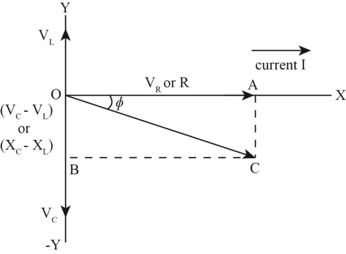
The inductive reactance is less than the capacitive reactance. Hence, the phasor angle is negative.
The phasor diagram of the circuit is shown below. 
Figure (1)
(b)
The phasor diagram if the capacitance is
(b)
Answer to Problem 66PQ
The phasor diagram of the circuit is shown below.
Explanation of Solution
Write the expression for the impedance.
Here,
Write the expression to calculate the inductive reactance.
Here,
Write the expression for the capacitive reactance.
Here,
Substitute the
Write the expression for maximum current in the circuit.
Here,
Write the expression for phase angle.
Conclusion:
Substitute
Substitute
Substitute
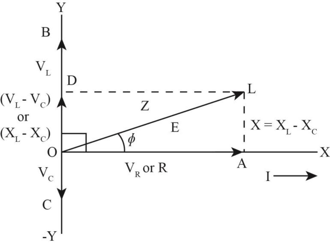
The phase angle is
The inductive reactance is less than the capacitive reactance. Hence, the phasor angle is negative.
The phasor diagram of the circuit is shown below.

Want to see more full solutions like this?
Chapter 33 Solutions
Physics for Scientists and Engineers: Foundations and Connections


- In the LC circuit in Figure 33.11, the inductance is L = 19.8 mH and the capacitance is C = 19.6 mF. At some moment, UB = UE= 17.5 mJ. a. What is the maximum charge stored by the capacitor? b. What is the maximum current in the circuit? c. At t = 0, the capacitor is fully charged. Write an expression for the charge stored by the capacitor as a function of lime. d. Write an expression for the current as a function of time.arrow_forwardThe self-inductance and capacitance of an LC circuit e 0.20 mH and 5.0 pF. What is the angular frequency at which the circuit oscillates?arrow_forwardFor an LC circuit, show that the total energy stored in the electric and magnetic fields is a constant given by Equation 33.28, Etot=Qmax2/2C=12LImax2.arrow_forward
- (i) When a particular inductor is connected to a source of sinusoidally varying emf with constant amplitude and a frequency of 60.0 Hz, the rms current is 3.00 A. What is the rms current if the source frequency is doubled? (a) 12.0 A (b) 6.00 A (c) 4.24 A (d) 3.00 A (e) 1.50 A (ii) Repeat part (i) assuming the load is a capacitor instead of an inductor. (iii) Repeat part (i) assuming the load is a resistor instead of an inductor.arrow_forwardIn an oscillating RLC circuit with L = 10 mH, C = 1.5 F , and R = 2.0 , how much time elapses before the amplitude of the oscillations drops to half its initial value?arrow_forwardAn oscillating LC circuit, with L = 1.5 mH and C = 0.01 μF, stores a maximum energy of 10 μJ. a/ What is the maximum current? b/ If resistance R = 100 mOhm is connected in series with L and C, what is the time for the maximum current to decay to 50% of its initial value.arrow_forward
- And LC circuit has an oscillation frequency f of 1.96 kHz. If the capacities is 3.64 micro farad, what is the inductance in mH? A. 58.7 mH B. 71.5 mH C. 2.82 mH D. 1.81 mH E. 6.93 mHarrow_forwardA sinusoidal voltage Δv = 45.0 sin(100t), where Δv is in volts and t is in seconds, is applied to a series RLC circuit with L = 170 mH, C = 99.0 µF, and R = 60.0 Ω. e) What If? For what value of the inductance (in H) in the circuit would the current lag the voltage by the same angle ? as that found in part (d)? f) What would be the maximum current (in A) in the circuit in this case?arrow_forwardIn an oscillating LC circuit, L = 25.0 mH and C = 7.80 mF. At time t 0 the current is 9.20 mA, the charge on the capacitor is 3.80 mC, and the capacitor is charging.What are (a) the total energy in the circuit, (b) the maximum charge on the capacitor, and (c) the maximum current? (d) If the charge on the capacitor is given by q = Q cos(vt + f), what is the phase angle f? (e) Suppose the data are the same, except that the capacitor is discharging at t = 0.What then is f?arrow_forward
- A 50.0 mH inductor is connected to an acgenerator with e=30.0 V.What is the amplitude of the resultingalternating current if the frequency of the emf is (a) 1.00 kHz and(b) 8.00 kHz?arrow_forwardThe current through the inductor of an LC circuit oscillates at ω = (3.2 π x 103) rad/s. If the inductance is 2.5 x 10⁻³H, what is the capacitance of the capacitor? A. 4.0 x 10⁻¹² F B. 4.0 x 10⁻⁶ F C. 1.6 X 10⁻⁵ F D. 2.5 x 10⁻⁷ F E. 2500 Farrow_forwardAn RLC circuit is used in a radio to tune into an FM station broadcasting at f = 99.7 MHz. The resistance in the circuit is R = 11.0 Ω, and the inductance is L = 1.44 µH. What capacitance should be used?arrow_forward
 Physics for Scientists and Engineers: Foundations...PhysicsISBN:9781133939146Author:Katz, Debora M.Publisher:Cengage Learning
 Physics for Scientists and Engineers, Technology ...PhysicsISBN:9781305116399Author:Raymond A. Serway, John W. JewettPublisher:Cengage Learning