Videos
(a)
The current in the circuit as a function of time.
(a)
Answer to Problem 72AP
The current in the circuit as a function of time is
Explanation of Solution
The circuit in which capacitor and inductor are short circuited and both the switch are closed is as shown below.
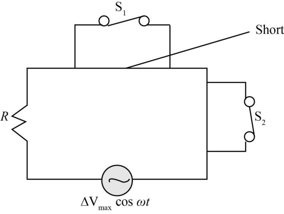
Figure-(1)
Write the expression to obtain the time varying voltage source.
Here,
Write the expression to obtain the current in the circuit as a function of time.
Here,
Substitute
Conclusion:
Therefore, the current in the circuit as a function of time is
(b)
The power delivered to the circuit.
(b)
Answer to Problem 72AP
The power delivered to the circuit is
Explanation of Solution
Write the expression to obtain the power delivered to the circuit.
Here,
Substitute
Conclusion:
Therefore, the power delivered to the circuit is
(c)
The current in the circuit as function of time if only switch
(c)
Answer to Problem 72AP
The current in the circuit as function of time if only switch
Explanation of Solution
The circuit in which switch
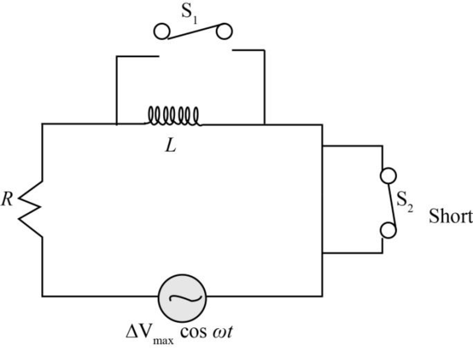
Figure-(2)
In case of inductor circuit, the phase difference between the current and voltage is
Write the expression to obtain the time varying voltage source in case
Here,
Write the expression to obtain the impedance in the circuit.
Here,
Write the expression to obtain the current in the circuit as a function of time.
Here,
Substitute
Conclusion:
Therefore, the current in the circuit as function of time if only switch
(d)
The capacitance of the capacitor when both the switches are closed and the current and voltage are in phase.
(d)
Answer to Problem 72AP
The capacitance of the capacitor when both the switches are open and the current and voltage are in phase is
Explanation of Solution
The circuit in which both the switches are open as shown in the figure below.
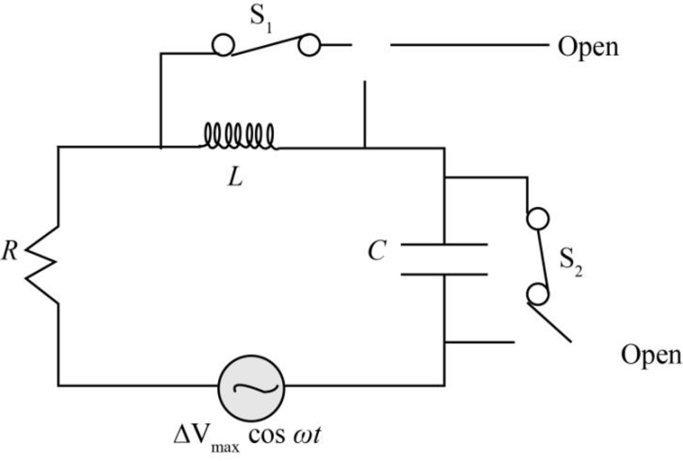
Figure-(3)
Write the expression obtain the impendence of the inductor.
Here,
Write the expression obtain the impendence of the capacitor.
Here,
When the current and voltage in the circuit are in phase, than the impendence of the inductor and the capacitor are equal.
Write the expression to obtain the relation the capacitance of the capacitor.
Here,
Substitute
Conclusion:
Therefore, the capacitance of the capacitor when both the switches are open and the current and voltage are in phase is
(e)
The impendence of the circuit when both the switches are open.
(e)
Answer to Problem 72AP
The impendence of the circuit when both the switches are open is
Explanation of Solution
Write the expression when both the switches are open.
Here,
Write the expression to obtain the impendence of the circuit.
Here,
Substitute
Conclusion:
Therefore, the impendence of the circuit when both the switches are open is
(f)
The maximum energy stored in the capacitor during the oscillations.
(f)
Answer to Problem 72AP
The maximum energy stored in the capacitor during the oscillations is
Explanation of Solution
Write the expression to obtain the voltage across the capacitor.
Here,
Substitute
Write the expression to obtain the maximum energy stored in the capacitor.
Here,
Substitute
Conclusion:
Therefore, the maximum energy stored in the capacitor during the oscillations is
(g)
The maximum energy stored in the inductor during the oscillations.
(g)
Answer to Problem 72AP
The maximum energy stored in the inductor during the oscillations is
Explanation of Solution
Write the expression to obtain the maximum energy stored in the inductor.
Here,
Substitute
Conclusion:
Therefore, the maximum energy stored in the inductor during the oscillations is
(h)
The phase difference between the current and the voltage when frequency of the voltage source is doubled.
(h)
Answer to Problem 72AP
The phase difference between the current and the voltage when frequency of the voltage source is doubled is
Explanation of Solution
Write the expression to obtain the phase difference between the current and voltage.
Here,
Substitute
As the frequency of the voltage source is doubled.
Substitute
Conclusion:
Therefore, the phase difference between the current and the voltage when frequency of the voltage source is doubled is
(i)
The frequency that makes the inductance reactance one-half the capacitive reactance.
(i)
Answer to Problem 72AP
The frequency that makes the inductance reactance one-half the capacitive reactance is
Explanation of Solution
Write the expression to obtain the frequency that makes the inductance reactance one-half the capacitive reactance.
Here,
Substitute
Conclusion:
Therefore, the frequency that makes the inductance reactance one-half the capacitive reactance is
Want to see more full solutions like this?
Chapter 33 Solutions
Physics: for Science.. With Modern. -Update (Looseleaf)


- When a wire carries an AC current with a known frequency, you can use a Rogowski coil to determine the amplitude Imax of the current without disconnecting the wire to shunt the current through a meter. The Rogowski coil, shown in Figure P23.8, simply clips around the wire. It consists of a toroidal conductor wrapped around a circular return cord. Let n represent the number of turns in the toroid per unit distance along it. Let A represent the cross-sectional area of the toroid. Let I(t) = Imax sin t represent the current to be measured. (a) Show that the amplitude of the emf induced in the Rogowski coil is Emax=0nAImax. (b) Explain why the wire carrying the unknown current need not be at the center of the Rogowski coil and why the coil will not respond to nearby currents that it does not enclose. Figure P23.8arrow_forwardIn the LC circuit in Figure 33.11, the inductance is L = 19.8 mH and the capacitance is C = 19.6 mF. At some moment, UB = UE= 17.5 mJ. a. What is the maximum charge stored by the capacitor? b. What is the maximum current in the circuit? c. At t = 0, the capacitor is fully charged. Write an expression for the charge stored by the capacitor as a function of lime. d. Write an expression for the current as a function of time.arrow_forwardProblems 71 and 72 paired. Figure P33.71 shows a series RLC circuit with a 25.0- resistor, a 430.0-mH inductor, and a 24.0-F capacitor connected to an AC source with Vmax = 60.0 V operating at 60.0 Hz. What is the maximum voltage across the a. resistor, b. inductor, and c. capacitor in the circuit? FIGURE P33.71 Problems 71 and 72.arrow_forward
- One application of an RL circuit is the generation of lime-varying high voltage from a low-volt age source as shown in Figure P32.82. (a) What is the current in the circuit a long time after the switch has been in position a? (b) Now the switch is thrown quickly from a to b. Compute the initial voltage across each resistor and across the inductor. (c) How much time elapses before the voltage across the inductor drops to 12.0 Y?arrow_forwardAn PLC series circuit with R=600 , L = 30 mH. and c=0.050F is driven by an ac source whose frequency and voltage amplitude are 500 Hz and 50 V, respectively, (a) What is the impedance of the circuit? (b) What is the amplitude of the current in the circuit? (c) What is the phase angle between the emf of the source and the current?arrow_forwardA 60.0- resistor is connected in series with a 30.0-F capacitor and a generator having a maximum voltage of 1.20 102 V and operating at 60.0 Hz. Find the (a) capacitive reactance of the circuit, (b) impedance of the circuit, and (c) maximum current in the circuit. (d) Does the voltage lead or lag the current? (e) How will putting an inductor in series with the existing capacitor and resistor affect the current? Explain.arrow_forward
- A series RLC circuit driven by a source with an amplitude of 120.0 V and a frequency of 50.0 Hz has an inductance of 787 mH, a resistance of 267 , and a capacitance of 45.7 F. a. What are the maximum current and the phase angle between the current and the source emf in this circuit? b. What are the maximum potential difference across the inductor and the phase angle between this potential difference and the current in the circuit? c. What are the maximum potential difference across the resistor and the phase angle between this potential difference and the current in this circuit? d. What are the maximum potential difference across the capacitor and the phase angle between this potential difference and the current in this circuit?arrow_forwardAn RLC series circuit has an impedance of 60 and a power factor of 0.50, with the voltage Lagging the current (a) Should a capacitor or an inductor be placed in series with the elements to raise the power factor of the circuit? (b) What is the value of the capacitance or self-inductance that will raise the power factor to unity?arrow_forward
 Physics for Scientists and Engineers, Technology ...PhysicsISBN:9781305116399Author:Raymond A. Serway, John W. JewettPublisher:Cengage Learning
 College PhysicsPhysicsISBN:9781305952300Author:Raymond A. Serway, Chris VuillePublisher:Cengage Learning
 College PhysicsPhysicsISBN:9781285737027Author:Raymond A. Serway, Chris VuillePublisher:Cengage Learning
 Physics for Scientists and Engineers: Foundations...PhysicsISBN:9781133939146Author:Katz, Debora M.Publisher:Cengage Learning
 Principles of Physics: A Calculus-Based TextPhysicsISBN:9781133104261Author:Raymond A. Serway, John W. JewettPublisher:Cengage Learning
 Physics for Scientists and Engineers with Modern ...PhysicsISBN:9781337553292Author:Raymond A. Serway, John W. JewettPublisher:Cengage Learning