Concept explainers
Videos
The difference in positions of two rays crossing the principal axis.
Answer to Problem 55P
The difference in positions of two rays crossing the principal axis is
Explanation of Solution
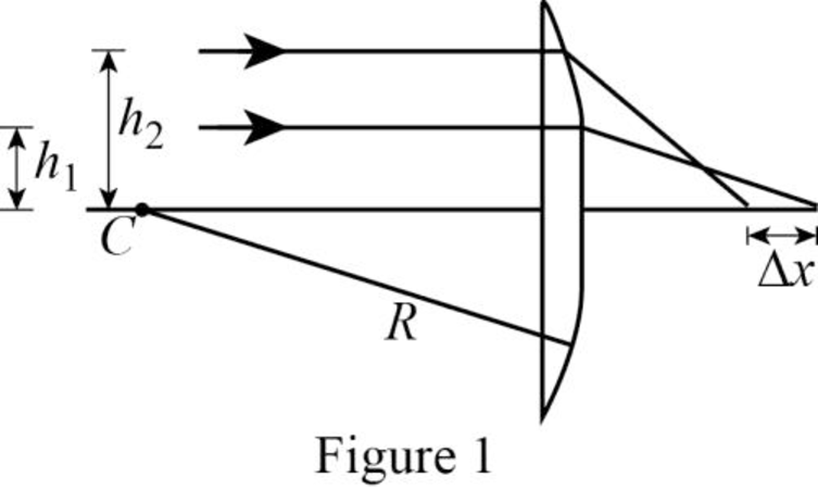
The following figure gives the ray diagram of the two rays.
Write the expression to find the angle of incidence of the first ray.
Here,
Write the relation between the angle of incidence of the first ray and the second ray.
Write the expression for the focal length of the first ray
Write the expression for the distance crossed by the principal axis from the vertex by the first ray.
Write the expression to find the angle of incidence of the second ray.
Here,
Write the relation between the angle of incidence of the first ray and the second ray.
Write the expression for the focal length of the second ray
Write the expression for the distance crossed by the principal axis from the vertex by the second ray.
Write the expression for the difference in positions of two rays crossing the principal axis .
Conclusion:
Substitute
Substitute
Substitute
Substitute
Substitute
Substitute
Substitute
Substitute
Substitute
Therefore, the difference in positions of two rays crossing the principal axis is
Want to see more full solutions like this?
Chapter 36 Solutions
Bundle: Physics for Scientists and Engineers with Modern Physics, Loose-leaf Version, 9th + WebAssign Printed Access Card, Multi-Term


- Figure P23.28 shows a curved surface separating a material with index of refraction n1 from a material with index n2. The surface forms an image I of object O. The ray shown in red passes through the surface along a radial line. Its angles of incidence and refraction are both zero, so its direction does not change at the surface. For the ray shown in blue, the direction changes according to n1 sin 1 = n2 sin 2. For paraxial rays, we assume 1 and 2 are small, so we may write n1 tan 1 n2 tan 2. The magnification is defined as M = h/h. Prove that the magnification is given by M = n1q/n2p. Figure P23.28arrow_forwardHow many times will the incident beam in Figure P34.33 (page 922) be reflected by each of the parallel mirrors? Figure P34.33arrow_forwardTwo rays travelling parallel to the principal axis strike a large plano-convex lens having a refractive index of 1.60 (Fig. P23.54). If the convex face is spherical, a ray near the edge does not pass through the local point (spherical aberration occurs). Assume this face has a radius of curvature of R = 20.0 cm and the two rays are at distances h1 = 0.500 cm and h2 = 12.0 cm from the principal axis. Find the difference x in the position where each crosses the principal axis. Figure P23.54arrow_forward
- Two rays travelling parallel to the principal axis strike a large plano-convex lens having a refractive index of 1.60 (Fig. P23.54). If the convex face is spherical, a ray near the edge does not pass through the local point (spherical aberration occurs). Assume this face has a radius of curvature of R = 20.0 cm and the two rays are at distances h1 = 0.500 cm and h2 = 12.0 cm from the principal axis. Find the difference x in the position where each crosses the principal axis. Figure P23.54arrow_forwardFigure P38.43 shows a concave meniscus lens. If |r1| = 8.50 cm and |r2| = 6.50 cm, find the focal length and determine whether the lens is converging or diverging. The lens is made of glass with index of refraction n = 1.55. CHECK and THINK: How do your answers change if the object is placed on the right side of the lens? FIGURE P38.43arrow_forwardTwo converging lenses having focal lengths of f1 = 10.0 cm and f2 = 20.0 cm are placed a distance d = 50.0 cm apart as shown in Figure P35.48. The image due to light passing through both lenses is to be located between the lenses at the position x = 31.0 cm indicated. (a) At what value of p should the object be positioned to the left of the first lens? (b) What is the magnification of the final image? (c) Is the final image upright or inverted? (d) Is the final image real or virtual?arrow_forward
- Figure P36.95 shows a thin converging lens for which the radii of curvature of its surfaces have magnitudes of 9.00 cm and 11.0 cm. The lens is in front of a concave spherical mirror with the radius of curvature R = 8.00 cm. Assume the focal points F1 and F2 of the lens are 5.00 cm from the center of the lens, (a) Determine the index of refraction of the lens material. The lens and mirror are 20.0 cm apart, and an object is placed 8.00 cm to the left of the lens. Determine (b) the position of the filial image and (c) its magnification as seen by the eye in the figure. (d) Is the final image inverted or upright? Explain.arrow_forwardIn Figure P35.30, a thin converging lens of focal length 14.0 cm forms an image of the square abed, which is he = hb = 10.0 cm high and lies between distances of pd = 20.0 cm and pa = 30.0 cm from the lens. Let a, b, c. and d represent the respective corners of the image. Let qa represent the image distance for points a and b, qd represent the image distance for points c and d, hb, represent the distance from point b to the axis, and hc represent the height of c. (a) Find qa, qd, hb, and hc. (b) Make a sketch of the image. (c) The area of the object is 100 cm2. By carrying out the following steps, you will evaluate the area of the image. Let q represent the image distance of any point between a and d, for which the object distance is p. Let h represent the distance from the axis to the point at the edge of the image between b and c at image distance q. Demonstrate that h=10.0q(114.01q) where h and q are in centimeters. (d) Explain why the geometric area of the image is given by qaqdhdq (e) Carry out the integration to find the area of the image. Figure P35.30arrow_forwardTwo rays traveling parallel to the principal axis strike a large plano-convex lens having a refractive index of 1.60 (Fig. P35.33). If the convex face is spherical, a ray near the edge does not pass through the focal point (spherical aberration occurs). Assume this face has a radius of curvature of R = 20.0 cm and the two rays are at distances h1 = 0.500 cm and h2 = 12.0 cm from the principal axis. Find the difference x in the positions where each crosses the principal axis. Figure P35.33arrow_forward
- Two converging lenses having focal length of f1 = 10.0 cm and f2 = 20.0 cm are placed d = 50.0 cm apart, as shown in Figure P23.44. The final image is to be located between the lenses, at the position x = 31.0 cm indicated. (a) How far to the left of the first lens should the object be positioned? (b) What is the overall magnification of the system? (c) Is the final image uptight or inserted? Figure P23.44arrow_forwardFigure P23.28 shows a curved surface separating a material with index of refraction n1 from a material with index n2. The surface forms an image I of object O. The ray shown in red passes through the surface along a radial line. Its angles of incidence and refraction are both zero, so its direction does not change at the surface. For the ray shown in blue, the direction changes according to n1 sin 1 = n2 sin 2. For paraxial rays, we assume 1 and 2 are small, so we may write n1 tan 1 n2 tan 2. The magnification is defined as M = h/h. Prove that the magnification is given by M = n1q/n2p. Figure P23.28arrow_forwardThe left face of a biconvex lens has a radius of curvature of magnitude 12.0 cm, and the right face has a radius of curvature of magnitude 18.0 cm. The index of refraction of the glass is 1.44. (a) Calculate the focal length of the lens for light incident from the left. (b) What If? After the lens is turned around to interchange the radii of curvature of the two faces, calculate the focal length of the lens for light incident from the left.arrow_forward
 Physics for Scientists and Engineers with Modern ...PhysicsISBN:9781337553292Author:Raymond A. Serway, John W. JewettPublisher:Cengage Learning
 College PhysicsPhysicsISBN:9781285737027Author:Raymond A. Serway, Chris VuillePublisher:Cengage Learning
 College PhysicsPhysicsISBN:9781305952300Author:Raymond A. Serway, Chris VuillePublisher:Cengage Learning
 Principles of Physics: A Calculus-Based TextPhysicsISBN:9781133104261Author:Raymond A. Serway, John W. JewettPublisher:Cengage Learning
 Physics for Scientists and Engineers, Technology ...PhysicsISBN:9781305116399Author:Raymond A. Serway, John W. JewettPublisher:Cengage Learning
 Physics for Scientists and Engineers: Foundations...PhysicsISBN:9781133939146Author:Katz, Debora M.Publisher:Cengage Learning