Concept explainers
Videos
Light rays strike a plane mirror at an angle of 45.0° as shown in Figure P37.15. At what angle should a second mirror be placed so that the reflected rays are parallel to the first mirror?
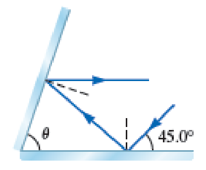
The angle at which the second mirror be placed so that the reflected rays are parallel to the first mirror.
Answer to Problem 15PQ
The angle at which the second mirror be placed so that the reflected rays are parallel to the first mirror is
Explanation of Solution
The following figure shows the reflection diagram.
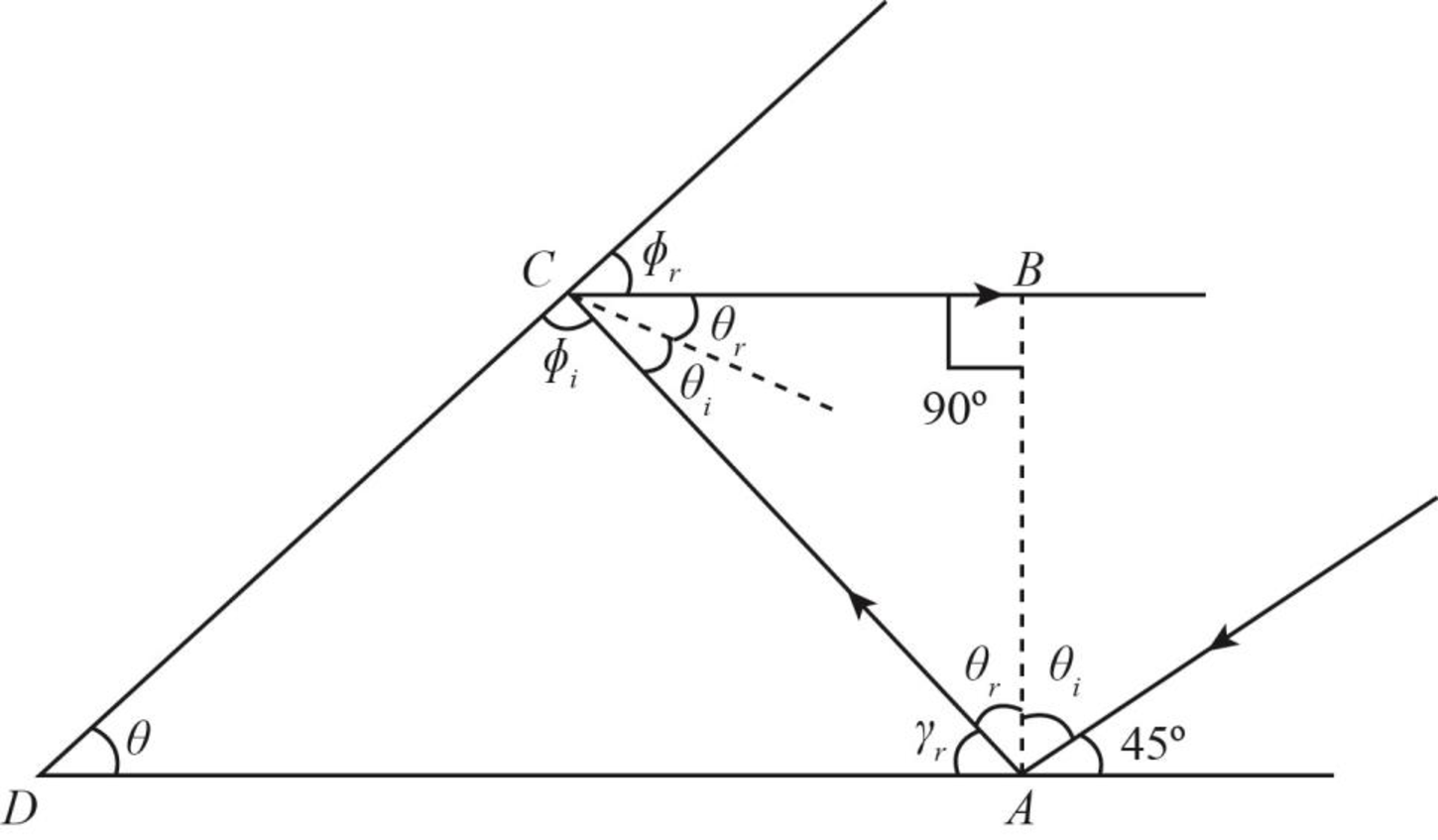
Figure-(1)
Here,
Calculate the angle from the above diagram.
According to law of reflection
Calculate the other angles from the above diagram.
From the above figure, the total angle in the triangle
For the second mirror, the total angle in a straight line is equal to
From the above figure, the total angle in the triangle
Conclusion:
Substitute
Substitute
Substitute
Substitute
Therefore, the angle at which the second mirror be placed so that the reflected rays are parallel to the first mirror is
Want to see more full solutions like this?
Chapter 37 Solutions
Physics for Scientist and Engineers (Foundations And Connection; Volume I and II) LLF edition


- A small convex mirror and a large concave mirror are separated by 1.00 m, and an object is placed 1.40 m to the left of the concave mirror (Fig. P37.69). The concave mirror forms an image of this object at distance di = 25.0 cm. This image is then reflected in the convex mirror, which forms an image a distance of 8.00 cm behind the convex mirror. What is the focal length of the small convex mirror? FIGURE P37.69arrow_forwardIf Joshs face is 30.0 cm in front of a concave shaving mirror creating an upright image 1.50 times as large as the object, what is the mirrors focal length? (a) 12.0 cm (b) 20.0 cm (c) 70.0 cm (d) 90.0 cm (e) none of those answersarrow_forwardAn observer to the right of the mirror-lens combination shown in Figure P36.89 (not to scale) sees two real images that are the same size and in the same location. One image is upright, and the other is inverted. Both images are 1.50 times larger than the object. The lens has a focal length of 10.0 cm. The lens and mirror are separated by 40.0 cm. Determine the focal length of the mirror.arrow_forward
- In Figure P35.30, a thin converging lens of focal length 14.0 cm forms an image of the square abed, which is he = hb = 10.0 cm high and lies between distances of pd = 20.0 cm and pa = 30.0 cm from the lens. Let a, b, c. and d represent the respective corners of the image. Let qa represent the image distance for points a and b, qd represent the image distance for points c and d, hb, represent the distance from point b to the axis, and hc represent the height of c. (a) Find qa, qd, hb, and hc. (b) Make a sketch of the image. (c) The area of the object is 100 cm2. By carrying out the following steps, you will evaluate the area of the image. Let q represent the image distance of any point between a and d, for which the object distance is p. Let h represent the distance from the axis to the point at the edge of the image between b and c at image distance q. Demonstrate that h=10.0q(114.01q) where h and q are in centimeters. (d) Explain why the geometric area of the image is given by qaqdhdq (e) Carry out the integration to find the area of the image. Figure P35.30arrow_forwardWhy is the following situation impossible? Consider the lensmirror combination shown in Figure P35.55. The lens has a focal length of fL = 0.200 m, and the mirror has a focal length of fM = 0.500 m. The lens and mirror are placed a distance d = 1.30 m apart, and an object is placed at p = 0.300 m from the lens. By moving a screen to various positions to the left of the lens, a student finds two different positions of the screen that produce a sharp image of the object. One of these positions corresponds to light leaving the object and traveling to the left through the lens. The other position corresponds to light traveling to the right from the object, reflecting from the mirror and then passing through the lens. Figure P35.55 Problem 55 and 57.arrow_forwardUse a ruler and a protractor to draw rays to find images in the following cases. (a) A point object located on the axis of a concave minor located at a point within the focal length from the vertex. (b) A point object located on the axis of a concave mirror located at a point farther than the focal length from the vertex. (c) A point object located on the axis of a convex mirror located at a point within the focal length from the vertex. (d) A point object located on the axis of a convex mirror located at a point farther than the focal length from the vertex. (e) Repeat (a)—(d) for a point object off the axis.arrow_forward
 Physics for Scientists and Engineers: Foundations...PhysicsISBN:9781133939146Author:Katz, Debora M.Publisher:Cengage Learning
 Glencoe Physics: Principles and Problems, Student...PhysicsISBN:9780078807213Author:Paul W. ZitzewitzPublisher:Glencoe/McGraw-Hill
 Principles of Physics: A Calculus-Based TextPhysicsISBN:9781133104261Author:Raymond A. Serway, John W. JewettPublisher:Cengage Learning
 Physics for Scientists and Engineers, Technology ...PhysicsISBN:9781305116399Author:Raymond A. Serway, John W. JewettPublisher:Cengage Learning
 Physics for Scientists and Engineers with Modern ...PhysicsISBN:9781337553292Author:Raymond A. Serway, John W. JewettPublisher:Cengage Learning
 Physics for Scientists and EngineersPhysicsISBN:9781337553278Author:Raymond A. Serway, John W. JewettPublisher:Cengage Learning