
Concept explainers
Videos
Determine a numerical value for each nodal voltage in the circuit of Fig. 4.44.
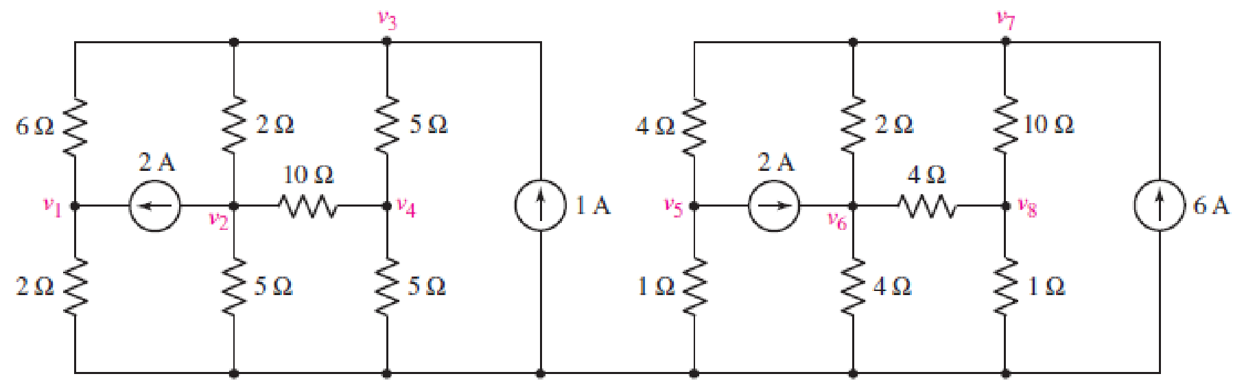
FIGURE 4.44
Find the numerical value of each nodal voltage.
Answer to Problem 14E
The nodal voltages are,
| S. No | Node | Nodal voltage |
| 1 | 3.078 V | |
| 2 | –2.349 V | |
| 3 | 0.3109 V | |
| 4 | –0.3454 V | |
|
5 | 1.02 V | |
|
6 | 9.217 V | |
| 7 | 13.095 V | |
| 8 | 2.6768 V |
Explanation of Solution
Calculation:
Refer to FIGURE 4.44 in the textbook.
Apply nodal analysis at node
Apply nodal analysis at node
Apply nodal analysis at node
Apply nodal analysis at node
Solve the equations by Cramer’s rule.
Find
Find
The value of
Find
The value of
Find
The value of
Find
The value of
Apply nodal analysis at node
Apply nodal analysis at node
Apply nodal analysis at node
Apply nodal analysis at node
Solve the equations by Cramer’s rule.
Find
Find
The value of
Find
The value of
Find
The value of
Find
The value of
Conclusion:
Thus, the nodal voltages are,
| S. No | Node | Nodal voltage |
| 1 | 3.078 V | |
| 2 | –2.349 V | |
| 3 | 0.3109 V | |
| 4 | –0.3454 V | |
|
5 | 1.02 V | |
|
6 | 9.217 V | |
| 7 | 13.095 V | |
| 8 | 2.6768 V |
Want to see more full solutions like this?
Chapter 4 Solutions
Loose Leaf for Engineering Circuit Analysis Format: Loose-leaf


- Given the circuit in Fig. 4.117, obtain the Norton equivalent as viewed from terminals:arrow_forwardFind the Thevenin equivalent circuit of the circuit in Fig. 4.34 to the left of the terminals.arrow_forwardUsing Thevenin’s theorem, find the equivalent circuit to the left of the terminals in the circuit of Fig. 4.30. Then find I.arrow_forward
- 4.57 Obtain the Thevenin and Norton equivalent circuitsat terminals a-b for the circuit in Fig. 4.123.arrow_forward4.48 Determine the Norton equivalent at terminals a-b forthe circuit in Fig. 4.115.arrow_forwardQuestion: 4.12 Determine vo in the circuit of Fig. 4.80 using the superposition principle.arrow_forward
- Teaching values through exhortation can be done with the help of ____________ a. Friends b. Computers c. Neighbors d. Stories with moral lessonsarrow_forward11 Kelvin Double Bridge is used for the measurement of larger value resistance. Select one: True Falsearrow_forwardNumber 4.29 Use source transformation to find correctly Vo in the circuit of Fig. 4.97.arrow_forward
 Introductory Circuit Analysis (13th Edition)Electrical EngineeringISBN:9780133923605Author:Robert L. BoylestadPublisher:PEARSON
 Delmar's Standard Textbook Of ElectricityElectrical EngineeringISBN:9781337900348Author:Stephen L. HermanPublisher:Cengage Learning
 Programmable Logic ControllersElectrical EngineeringISBN:9780073373843Author:Frank D. PetruzellaPublisher:McGraw-Hill Education
 Fundamentals of Electric CircuitsElectrical EngineeringISBN:9780078028229Author:Charles K Alexander, Matthew SadikuPublisher:McGraw-Hill Education
 Electric Circuits. (11th Edition)Electrical EngineeringISBN:9780134746968Author:James W. Nilsson, Susan RiedelPublisher:PEARSON
 Engineering ElectromagneticsElectrical EngineeringISBN:9780078028151Author:Hayt, William H. (william Hart), Jr, BUCK, John A.Publisher:Mcgraw-hill Education,