Computer Science Illuminated
6th Edition
ISBN: 9781284055917
Author: Nell Dale, John Lewis
Publisher: Jones & Bartlett Learning
expand_more
expand_more
format_list_bulleted
Videos
Expert Solution & Answer
Chapter 4, Problem 35E
Explanation of Solution
Gates:
- A gate is a device which is used to perform the basic logical operation.
- It accepts one or more input signals and generates single output signal.
- It contains several types of gates.
- Six types of gates are most commonly used. They are:
- NOT gate
- AND gate
- OR gate
- XOR gate
- NAND gate
- NOR gate
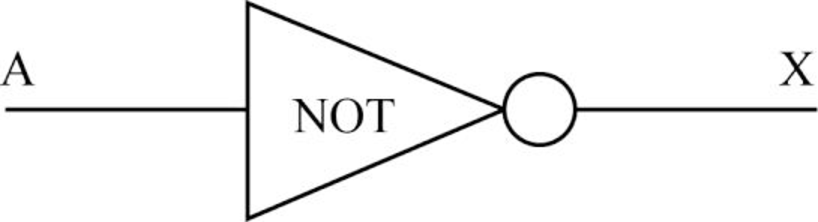
- NOT gate:
- A NOT gate accepts only one input value to generate single output value.
- When the input is 0, then the output is 1. The output of the NOT gate is the inversion of its input.
- So, it is also referred to as inverter.
- It is represented in three ways:
- In “Boolean expression”, the NOT operation is expressed using the “
- In “Boolean expression”, the NOT operation is expressed using the “
Where A is the input and X is the output.
- The “logic diagram” for NOT gate takes A as input and generates a single X as output:
- The “Truth table” for the NOT gate:
| A | |
| 0 | 1 |
| 1 | 0 |
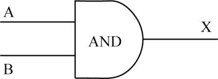
- AND gate:
- An AND gate accepts two inputs and generates a single output.
- When both the inputs are 1, then the output is 1. Otherwise, the output is 0.
- It is represented in three ways:
- In “Boolean expression”, the AND operation is expressed using the “.” dot operator or “*” asterisk operator.
Where A and B are the inputs and X is the output.
- The “logic diagram” for AND gate takes two inputs and generates a single output:
- The “Truth table” for the AND gate:
| A | B | |
| 0 | 0 | 0 |
| 0 | 1 | 0 |
| 1 | 0 | 0 |
| 1 | 1 | 1 |
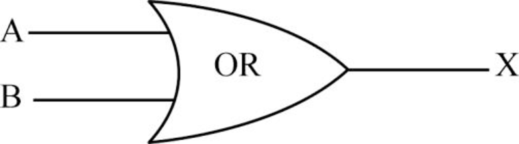
- OR gate:
- An OR gate accepts two inputs and generates a single output.
- When both the inputs are 0, then the output is 0. Otherwise, the output is 1.
- It is represented in three ways:
- In “Boolean expression”, the OR operation is expressed using the “+” plus sign.
- In “Boolean expression”, the OR operation is expressed using the “+” plus sign.
Where A and B are the inputs and X is the output.
- The “logic diagram” for OR gate takes two inputs and generates a single output:
- The “Truth table” for the OR gate:
| A | B | |
| 0 | 0 | 0 |
| 0 | 1 | 1 |
| 1 | 0 | 1 |
| 1 | 1 | 1 |
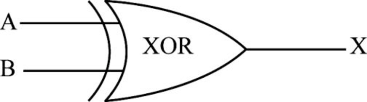
- XOR gate:
- An XOR gate accepts two inputs and produces a single output.
- When both the inputs are same, then the output is 0. Otherwise, the output is 1.
- It is represented in three ways:
- In “Boolean expression”, the XOR operation is expressed by using the “
- In “Boolean expression”, the XOR operation is expressed by using the “
Where A and B are the inputs and X is the output.
- The “logic diagram” for XOR gate takes two inputs and generates a single output:
- The “Truth table” for the XOR gate:
| A | B | X = A |
| 0 | 0 | 0 |
| 0 | 1 | 1 |
| 1 | 0 | 1 |
| 1 | 1 | 0 |
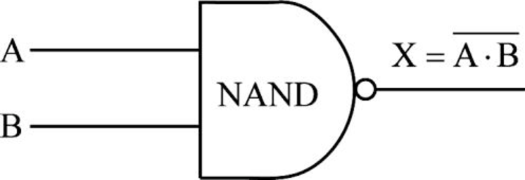
- NAND gate:
- The NAND gate accepts two inputs and produces a single output.
- It produces the opposite results of an AND gate.
- If both the inputs are 1, then the output is 0. Otherwise, the output is 1.
- It is represented in three ways:
- The “Boolean expression” for NAND gate:
- No specific symbol is used to express the NAND operation.
- The expression for NAND is the negation of an AND operation.
- The “Boolean expression” for NAND gate:
Where A and B are the inputs and X is the output.
- The “logic diagram” for NAND gate:
- It takes two inputs and generates a single output.
- The “Truth table” for the NAND gate:
| A | B | |
| 0 | 0 | 1 |
| 0 | 1 | 1 |
| 1 | 0 | 1 |
| 1 | 1 | 0 |
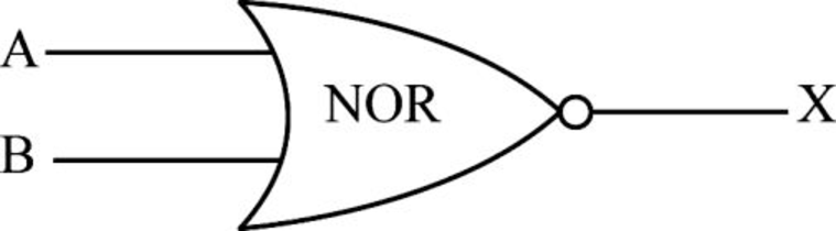
- NOR gate:
- The NOR gate accepts two inputs and produces a single output.
- It produces the opposite results of an OR gate.
- If both the inputs are 0, then only the output is 1. Otherwise, the output is 0.
- It is represented in three ways:
- In “Boolean expression”,
- No specific symbol is used to express the NOR operation.
- The expression for NOR is the negation of an OR operation.
- In “Boolean expression”,
Where A and B are the inputs and X is the output.
- The “logic diagram” for NOR gate takes two inputs and generates a single output:
- The “Truth table” for the NOR gate:
| A | B | |
| 0 | 0 | 1 |
| 0 | 1 | 0 |
| 1 | 0 | 0 |
| 1 | 1 | 0 |
Want to see more full solutions like this?
Subscribe now to access step-by-step solutions to millions of textbook problems written by subject matter experts!
Chapter 4 Solutions
Computer Science Illuminated
Ch. 4 - Prob. 1ECh. 4 - Prob. 2ECh. 4 - Prob. 3ECh. 4 - Prob. 4ECh. 4 - Prob. 5ECh. 4 - Prob. 6ECh. 4 - Prob. 7ECh. 4 - Prob. 8ECh. 4 - Prob. 9ECh. 4 - Prob. 10E
Ch. 4 - Prob. 11ECh. 4 - Prob. 12ECh. 4 - Prob. 13ECh. 4 - Prob. 14ECh. 4 - Prob. 15ECh. 4 - Prob. 16ECh. 4 - Prob. 17ECh. 4 - Prob. 18ECh. 4 - Prob. 19ECh. 4 - Prob. 20ECh. 4 - Prob. 21ECh. 4 - Prob. 22ECh. 4 - Prob. 23ECh. 4 - Prob. 24ECh. 4 - Prob. 25ECh. 4 - Prob. 26ECh. 4 - Prob. 27ECh. 4 - Prob. 28ECh. 4 - Prob. 29ECh. 4 - Prob. 30ECh. 4 - Prob. 31ECh. 4 - Prob. 32ECh. 4 - Prob. 33ECh. 4 - Prob. 34ECh. 4 - Prob. 35ECh. 4 - Prob. 36ECh. 4 - Prob. 37ECh. 4 - Prob. 38ECh. 4 - Prob. 39ECh. 4 - Prob. 40ECh. 4 - Prob. 41ECh. 4 - Prob. 42ECh. 4 - Prob. 43ECh. 4 - Prob. 44ECh. 4 - Prob. 45ECh. 4 - Prob. 46ECh. 4 - Prob. 47ECh. 4 - Prob. 48ECh. 4 - Prob. 49ECh. 4 - Prob. 50ECh. 4 - Prob. 51ECh. 4 - Prob. 52ECh. 4 - Prob. 53ECh. 4 - Prob. 54ECh. 4 - Prob. 55ECh. 4 - Prob. 56ECh. 4 - Prob. 57ECh. 4 - Prob. 58ECh. 4 - Prob. 59ECh. 4 - Prob. 60ECh. 4 - Prob. 61ECh. 4 - Prob. 62ECh. 4 - Prob. 63ECh. 4 - Prob. 64ECh. 4 - Prob. 65ECh. 4 - Prob. 66ECh. 4 - Prob. 67ECh. 4 - Prob. 68ECh. 4 - Prob. 69ECh. 4 - Prob. 70ECh. 4 - Prob. 71ECh. 4 - Prob. 72ECh. 4 - Prob. 73ECh. 4 - Prob. 1TQCh. 4 - Prob. 2TQCh. 4 - Prob. 3TQCh. 4 - Prob. 4TQ
Knowledge Booster


Learn more about
Need a deep-dive on the concept behind this application? Look no further. Learn more about this topic, computer-science and related others by exploring similar questions and additional content below.Recommended textbooks for you
 Database System ConceptsComputer ScienceISBN:9780078022159Author:Abraham Silberschatz Professor, Henry F. Korth, S. SudarshanPublisher:McGraw-Hill Education
 Starting Out with Python (4th Edition)Computer ScienceISBN:9780134444321Author:Tony GaddisPublisher:PEARSON
 Digital Fundamentals (11th Edition)Computer ScienceISBN:9780132737968Author:Thomas L. FloydPublisher:PEARSON
 C How to Program (8th Edition)Computer ScienceISBN:9780133976892Author:Paul J. Deitel, Harvey DeitelPublisher:PEARSON
 Database Systems: Design, Implementation, & Manag...Computer ScienceISBN:9781337627900Author:Carlos Coronel, Steven MorrisPublisher:Cengage Learning
 Programmable Logic ControllersComputer ScienceISBN:9780073373843Author:Frank D. PetruzellaPublisher:McGraw-Hill Education
Database System Concepts
Computer Science
ISBN:9780078022159
Author:Abraham Silberschatz Professor, Henry F. Korth, S. Sudarshan
Publisher:McGraw-Hill Education
Starting Out with Python (4th Edition)
Computer Science
ISBN:9780134444321
Author:Tony Gaddis
Publisher:PEARSON
Digital Fundamentals (11th Edition)
Computer Science
ISBN:9780132737968
Author:Thomas L. Floyd
Publisher:PEARSON
C How to Program (8th Edition)
Computer Science
ISBN:9780133976892
Author:Paul J. Deitel, Harvey Deitel
Publisher:PEARSON
Database Systems: Design, Implementation, & Manag...
Computer Science
ISBN:9781337627900
Author:Carlos Coronel, Steven Morris
Publisher:Cengage Learning
Programmable Logic Controllers
Computer Science
ISBN:9780073373843
Author:Frank D. Petruzella
Publisher:McGraw-Hill Education
Boolean Algebra - Digital Logic and Logic Families - Industrial Electronics; Author: Ekeeda;https://www.youtube.com/watch?v=u7XnJos-_Hs;License: Standard YouTube License, CC-BY
Boolean Algebra 1 – The Laws of Boolean Algebra; Author: Computer Science;https://www.youtube.com/watch?v=EPJf4owqwdA;License: Standard Youtube License