
Mastering Engineering with Pearson eText -- Standalone Access Card -- for Electrical Engineering: Principles & Applications
7th Edition
ISBN: 9780134486970
Author: Allan R. Hambley
Publisher: PEARSON
expand_more
expand_more
format_list_bulleted
Concept explainers
Videos
Textbook Question
Chapter 4, Problem 4.11P
We know that the capacitor shown in Figure P4.11 is charged to a voltage of 10 V prior to t = 0.
- Find expressions for the voltage across the capacitor
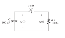
Figure P4.11
Expert Solution & Answer

Trending nowThis is a popular solution!

Students have asked these similar questions
The capacitor model we have used so far has beentreated as an ideal circuit element. A more accuratemodel for a capacitor is shown in Figure P4.67. Theideal capacitor, C, has a large “leakage” resistance, RC,in parallel with it. RC models the leakage currentthrough the capacitor. R1 and R2 represent the leadwire resistances, and L1 and L2 represent the lead wireinductances.a. If C = 1 μF, RC = 100 MΩ, R1 = R2 = 1 μΩ andL1 = L2 = 0.1 μH, find the equivalent impedanceseen at the terminals a and b as a function offrequency ω.b. Find the range of frequencies for which Zab iscapacitive, i.e., Xab > 10|Rab.Hint: Assume that RC is is much greater than 1/wC so thatyou can replace RC by an infinite resistance in part b.
Use the defining law for a capacitor to find the current iC(t) corresponding to the voltage shown in Figure P4.27. Sketch your result.
Consider the circuit of Figure P4.17, in which the switch instantaneously moves back and forth between contacts A and B, spending 2 seconds in each position. Thus, the capacitor repeatedly charges for 2 seconds and then discharges for 2 seconds. Assume that v C ( 0 )=0 and that the switch moves to position A at t=0. Determine v C ( 2 ), v C ( 4 ), v C ( 6 ), and v C ( 8 ).
Chapter 4 Solutions
Mastering Engineering with Pearson eText -- Standalone Access Card -- for Electrical Engineering: Principles & Applications
Ch. 4 - Suppose we have a capacitance C discharging...Ch. 4 - The dielectric materials used in real capacitors...Ch. 4 - The initial voltage across the capacitor shown in...Ch. 4 - A 100F capacitance is initially charged to 1000 V....Ch. 4 - At t = 0, a charged 10{ F capacitance is connected...Ch. 4 - At time t1 , a capacitance C is charged to a...Ch. 4 - Given an initially charged capacitance that begins...Ch. 4 - The initial voltage across the capacitor shown in...Ch. 4 - In physics, the half-life is often used to...Ch. 4 - We know that a 50F capacitance is charged to an...
Ch. 4 - We know that the capacitor shown in Figure P4.11...Ch. 4 - The purchasing power P of a certain unit of...Ch. 4 - Derive an expression for vC(t) in the circuit of...Ch. 4 - Suppose that at t= 0, we connect an uncharged 10 F...Ch. 4 - Suppose we have a capacitance C that is charged to...Ch. 4 - A person shuffling across a dry carpet can be...Ch. 4 - Prob. 4.17PCh. 4 - Consider the circuit shown in Figure P4.18. Prior...Ch. 4 - List the steps for dc steady-state analysis of RLC...Ch. 4 - Explain why we replace capacitances with open...Ch. 4 - Solve for the steady-state values of i1, i2, and...Ch. 4 - Consider the circuit shown in Figure P4.22. What...Ch. 4 - In the circuit of Figure P4.23, the switch is in...Ch. 4 - The circuit shown in Figure P4.24 has been set up...Ch. 4 - Solve for the steady-state values of i1 , i2, i3,...Ch. 4 - The circuit shown in Figure P4.26 is operating in...Ch. 4 - Prob. 4.27PCh. 4 - Consider the circuit of Figure P4.28 in which the...Ch. 4 - For the circuit shown in Figure P4.29, the switch...Ch. 4 - Consider the circuit of Figure P4.30 in which the...Ch. 4 - Give the expression for the time constant of a...Ch. 4 - A circuit consists of switches that open or close...Ch. 4 - The circuit shown in Figure P4.33 is operating in...Ch. 4 - Consider the circuit shown in Figure P4.34. The...Ch. 4 - Repeat Problem P4.34 given iL(0)=0A .Ch. 4 - Real inductors have series resistance associated...Ch. 4 - Determine expressions for and sketch is(t) to...Ch. 4 - For the circuit shown in Figure P4.38,, find an...Ch. 4 - The circuit shown in Figure P4.39 is operating in...Ch. 4 - Consider the circuit shown in Figure P4.40. A...Ch. 4 - Due to components not shown in the figure, the...Ch. 4 - The switch shown in Figure P4.42 has been closed...Ch. 4 - Determine expressions for and sketch vR(t) to...Ch. 4 - What are the steps in solving a circuit having a...Ch. 4 - Prob. 4.45PCh. 4 - Solve for vC(t) for t > 0 in the circuit of Figure...Ch. 4 - Solve for v(t) for t > 0 in the circuit of Figure...Ch. 4 - Prob. 4.48PCh. 4 - Consider the circuit shown inFigure P4.49. The...Ch. 4 - Consider the circuit shown in Figure P4.50. The...Ch. 4 - The voltage source shown in Figure P4.51 is called...Ch. 4 - Determine the form of the particular solution for...Ch. 4 - Determine the form of the particular solution for...Ch. 4 - Prob. 4.54PCh. 4 - Prob. 4.55PCh. 4 - How can first-or second-order circuits be...Ch. 4 - Prob. 4.57PCh. 4 - Prob. 4.58PCh. 4 - Prob. 4.59PCh. 4 - Sketch a step response for a second-order system...Ch. 4 - A dc source is connected to a series RLC circuit...Ch. 4 - Repeat Problem P4.61 for R = 40 .Ch. 4 - Repeat Problem P4.61 for R = 20 .Ch. 4 - Prob. 4.64PCh. 4 - Repeat Problem P4.64 for R=50 .Ch. 4 - Repeat Problem P4.64 for R=500 .Ch. 4 - Solve for i(t) for t > 0 in the circuit of Figure...Ch. 4 - Prob. 4.68PCh. 4 - Prob. 4.69PCh. 4 - Prob. 4.70PCh. 4 - Use MATLAB to derive an expression for vc(t)in the...Ch. 4 - Prob. 4.72PCh. 4 - Consider the circuit shown in FigureP4.50 in which...Ch. 4 - Prob. 4.74PCh. 4 - Prob. 4.75PCh. 4 - Use MATLAB to solve for the mesh currents in the...Ch. 4 - The switch m the circuit shown in Figure T4.1 is...Ch. 4 - Prob. 4.2PTCh. 4 - Consider the circuit shown in Figure T4.3. Figure...Ch. 4 - Consider the circuit shown in Figure T4.4 in which...Ch. 4 - Write the MATLAB commands to obtain the solution...
Additional Engineering Textbook Solutions
Find more solutions based on key concepts
Find I0 and I1 in the circuit in Fig.P2.12.
Basic Engineering Circuit Analysis
Write the nodal equations for the network of Fig. 8.137 using the general approach. Find the nodal voltages usi...
Introductory Circuit Analysis (13th Edition)
For the “tank” circuit in Fig. 14.79, find the resonant frequency.
Figure 14.79
For Probs. 14.39, 14.71, and 1...
Fundamentals of Electric Circuits
What is the color code for a 365- five-band precision resistor with a tolerance of 5 percent?
ELECTRICITY FOR TRADES (LOOSELEAF)
The voltage source of the circuit shown in Fig. P1.29 is given by s(t)=25cos(4104t45)(V). Obtain an expression ...
Fundamentals of Applied Electromagnetics (7th Edition)
When travelers from the USA and Canada visit Europe, they encounter a different power distribution system. Wall...
Electric machinery fundamentals
Knowledge Booster


Learn more about
Need a deep-dive on the concept behind this application? Look no further. Learn more about this topic, electrical-engineering and related others by exploring similar questions and additional content below.Similar questions
- Determine expressions for and sketch v R ( t ) to scale versus time for the circuit of Figure P4.43. The circuit is operating in steady state with the switch closed prior to t=0. Consider the time interval −1≤t≤5 ms.arrow_forwardIf the plots shown in Figure P4.18 are the voltageacross and the current through an ideal capacitor,determine the capacitance.arrow_forwardThe initial voltage across the capacitor shown in Figure P4.3 is v C ( 0+ )=−10 V. Find anexpression for the voltage across the capacitor as a function of time. Also, determine the time t0at which the voltage crosses zero.arrow_forward
- Due to components not shown in the figure, the circuit of Figure P4.41 has i L ( 0 )= I i . a. Write an expression for i L (t) for t≥0. b. Find an expression for the power delivered to the resistance as a function of time. c. Integrate the power delivered to the resistance from t=0 to t=∞, and show that the result is equal to the initial energy stored in the inductancearrow_forwardConsider the circuit shown in Figure P4.40. A voltmeter (VM) is connected across the inductance. The switch has been closed for a long time. When the switch is opened, an arc appears across the switch contacts. Explain why. Assuming an ideal switch and inductor, what voltage appears across the inductor when the switch is opened? What could happen to the voltmeter when the switch opens?arrow_forwardThe voltage across an inductor plotted as a functionof time is shown in Figure P4.14. If L = 0.75 mH,determine the current through the inductor att = 15 μs.arrow_forward
- The initial voltage across the capacitor shown in Figure P4.3 is v C ( 0+ )=0. Find an expression for the voltage across the capacitor as a function of time, and sketch to scale versus timearrow_forwardIf the waveform shown in Figure P4.15 is thevoltage across a capacitor plotted as a function of timewithvPK = 20V, T = 40 μs, C = 680nFdetermine and plot the waveform for the currentthrough the capacitor as a function of time.arrow_forwardThe current waveform shown in Figure P4.23 flowsthrough a 2-H inductor. Plot the inductor voltage vL(t).arrow_forward
- If the plots shown in Figure P4.19 are the voltageacross and the current through an ideal inductor,determine the inductance.arrow_forwardIn Figure P4.64, let R=500 Ω. Using the inductor current, derive the Characteristic Equation.arrow_forwardAt t=0 a charged 10{μF capacitance is connected to a voltmeter, as shown in Figure P4.5. The meter can be modeled as a resistance. At t=0 the meter reads 50 V. At t=30s, the reading is 25 V. Find the resistance of the voltmeter.arrow_forward
arrow_back_ios
SEE MORE QUESTIONS
arrow_forward_ios
Recommended textbooks for you
 Introductory Circuit Analysis (13th Edition)Electrical EngineeringISBN:9780133923605Author:Robert L. BoylestadPublisher:PEARSON
 Delmar's Standard Textbook Of ElectricityElectrical EngineeringISBN:9781337900348Author:Stephen L. HermanPublisher:Cengage Learning
 Programmable Logic ControllersElectrical EngineeringISBN:9780073373843Author:Frank D. PetruzellaPublisher:McGraw-Hill Education
 Fundamentals of Electric CircuitsElectrical EngineeringISBN:9780078028229Author:Charles K Alexander, Matthew SadikuPublisher:McGraw-Hill Education
 Electric Circuits. (11th Edition)Electrical EngineeringISBN:9780134746968Author:James W. Nilsson, Susan RiedelPublisher:PEARSON
 Engineering ElectromagneticsElectrical EngineeringISBN:9780078028151Author:Hayt, William H. (william Hart), Jr, BUCK, John A.Publisher:Mcgraw-hill Education,
Introductory Circuit Analysis (13th Edition)
Electrical Engineering
ISBN:9780133923605
Author:Robert L. Boylestad
Publisher:PEARSON
Delmar's Standard Textbook Of Electricity
Electrical Engineering
ISBN:9781337900348
Author:Stephen L. Herman
Publisher:Cengage Learning
Programmable Logic Controllers
Electrical Engineering
ISBN:9780073373843
Author:Frank D. Petruzella
Publisher:McGraw-Hill Education
Fundamentals of Electric Circuits
Electrical Engineering
ISBN:9780078028229
Author:Charles K Alexander, Matthew Sadiku
Publisher:McGraw-Hill Education
Electric Circuits. (11th Edition)
Electrical Engineering
ISBN:9780134746968
Author:James W. Nilsson, Susan Riedel
Publisher:PEARSON
Engineering Electromagnetics
Electrical Engineering
ISBN:9780078028151
Author:Hayt, William H. (william Hart), Jr, BUCK, John A.
Publisher:Mcgraw-hill Education,
Capacitors Explained - The basics how capacitors work working principle; Author: The Engineering Mindset;https://www.youtube.com/watch?v=X4EUwTwZ110;License: Standard YouTube License, CC-BY