
Mastering Engineering with Pearson eText -- Standalone Access Card -- for Electrical Engineering: Principles & Applications
7th Edition
ISBN: 9780134486970
Author: Allan R. Hambley
Publisher: PEARSON
expand_more
expand_more
format_list_bulleted
Concept explainers
Videos
Textbook Question
Chapter 4, Problem 4.29P
For the circuit shown in Figure P4.29, the switch is closed for a long time prior to t = 0. Find expressions for v(t) and sketch it to scale for
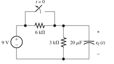
Figure P4.29
Expert Solution & Answer

Trending nowThis is a popular solution!

Students have asked these similar questions
Determine expressions for and sketch v R ( t ) to scale versus time for the circuit of Figure P4.43. The circuit is operating in steady state with the switch closed prior to t=0. Consider the time interval −1≤t≤5 ms.
The circuit shown in Figure P4.39 is operating in steady state with the switch closed prior to t=0. Find expressions for i L ( t ) for t<0 and for t≥0. Sketch iL(t) to scale versus time
Consider the circuit of Figure P4.17, in which the switch instantaneously moves back and forth between contacts A and B, spending 2 seconds in each position. Thus, the capacitor repeatedly charges for 2 seconds and then discharges for 2 seconds. Assume that v C ( 0 )=0 and that the switch moves to position A at t=0. Determine v C ( 2 ), v C ( 4 ), v C ( 6 ), and v C ( 8 ).
Chapter 4 Solutions
Mastering Engineering with Pearson eText -- Standalone Access Card -- for Electrical Engineering: Principles & Applications
Ch. 4 - Suppose we have a capacitance C discharging...Ch. 4 - The dielectric materials used in real capacitors...Ch. 4 - The initial voltage across the capacitor shown in...Ch. 4 - A 100F capacitance is initially charged to 1000 V....Ch. 4 - At t = 0, a charged 10{ F capacitance is connected...Ch. 4 - At time t1 , a capacitance C is charged to a...Ch. 4 - Given an initially charged capacitance that begins...Ch. 4 - The initial voltage across the capacitor shown in...Ch. 4 - In physics, the half-life is often used to...Ch. 4 - We know that a 50F capacitance is charged to an...
Ch. 4 - We know that the capacitor shown in Figure P4.11...Ch. 4 - The purchasing power P of a certain unit of...Ch. 4 - Derive an expression for vC(t) in the circuit of...Ch. 4 - Suppose that at t= 0, we connect an uncharged 10 F...Ch. 4 - Suppose we have a capacitance C that is charged to...Ch. 4 - A person shuffling across a dry carpet can be...Ch. 4 - Prob. 4.17PCh. 4 - Consider the circuit shown in Figure P4.18. Prior...Ch. 4 - List the steps for dc steady-state analysis of RLC...Ch. 4 - Explain why we replace capacitances with open...Ch. 4 - Solve for the steady-state values of i1, i2, and...Ch. 4 - Consider the circuit shown in Figure P4.22. What...Ch. 4 - In the circuit of Figure P4.23, the switch is in...Ch. 4 - The circuit shown in Figure P4.24 has been set up...Ch. 4 - Solve for the steady-state values of i1 , i2, i3,...Ch. 4 - The circuit shown in Figure P4.26 is operating in...Ch. 4 - Prob. 4.27PCh. 4 - Consider the circuit of Figure P4.28 in which the...Ch. 4 - For the circuit shown in Figure P4.29, the switch...Ch. 4 - Consider the circuit of Figure P4.30 in which the...Ch. 4 - Give the expression for the time constant of a...Ch. 4 - A circuit consists of switches that open or close...Ch. 4 - The circuit shown in Figure P4.33 is operating in...Ch. 4 - Consider the circuit shown in Figure P4.34. The...Ch. 4 - Repeat Problem P4.34 given iL(0)=0A .Ch. 4 - Real inductors have series resistance associated...Ch. 4 - Determine expressions for and sketch is(t) to...Ch. 4 - For the circuit shown in Figure P4.38,, find an...Ch. 4 - The circuit shown in Figure P4.39 is operating in...Ch. 4 - Consider the circuit shown in Figure P4.40. A...Ch. 4 - Due to components not shown in the figure, the...Ch. 4 - The switch shown in Figure P4.42 has been closed...Ch. 4 - Determine expressions for and sketch vR(t) to...Ch. 4 - What are the steps in solving a circuit having a...Ch. 4 - Prob. 4.45PCh. 4 - Solve for vC(t) for t > 0 in the circuit of Figure...Ch. 4 - Solve for v(t) for t > 0 in the circuit of Figure...Ch. 4 - Prob. 4.48PCh. 4 - Consider the circuit shown inFigure P4.49. The...Ch. 4 - Consider the circuit shown in Figure P4.50. The...Ch. 4 - The voltage source shown in Figure P4.51 is called...Ch. 4 - Determine the form of the particular solution for...Ch. 4 - Determine the form of the particular solution for...Ch. 4 - Prob. 4.54PCh. 4 - Prob. 4.55PCh. 4 - How can first-or second-order circuits be...Ch. 4 - Prob. 4.57PCh. 4 - Prob. 4.58PCh. 4 - Prob. 4.59PCh. 4 - Sketch a step response for a second-order system...Ch. 4 - A dc source is connected to a series RLC circuit...Ch. 4 - Repeat Problem P4.61 for R = 40 .Ch. 4 - Repeat Problem P4.61 for R = 20 .Ch. 4 - Prob. 4.64PCh. 4 - Repeat Problem P4.64 for R=50 .Ch. 4 - Repeat Problem P4.64 for R=500 .Ch. 4 - Solve for i(t) for t > 0 in the circuit of Figure...Ch. 4 - Prob. 4.68PCh. 4 - Prob. 4.69PCh. 4 - Prob. 4.70PCh. 4 - Use MATLAB to derive an expression for vc(t)in the...Ch. 4 - Prob. 4.72PCh. 4 - Consider the circuit shown in FigureP4.50 in which...Ch. 4 - Prob. 4.74PCh. 4 - Prob. 4.75PCh. 4 - Use MATLAB to solve for the mesh currents in the...Ch. 4 - The switch m the circuit shown in Figure T4.1 is...Ch. 4 - Prob. 4.2PTCh. 4 - Consider the circuit shown in Figure T4.3. Figure...Ch. 4 - Consider the circuit shown in Figure T4.4 in which...Ch. 4 - Write the MATLAB commands to obtain the solution...
Knowledge Booster


Learn more about
Need a deep-dive on the concept behind this application? Look no further. Learn more about this topic, electrical-engineering and related others by exploring similar questions and additional content below.Similar questions
- For the circuit shown in Figure P4.29, the switch is closed for a long time prior to t=0.Find expressions for vC(t) and sketch it to scale for −80≤t≤160 ms.arrow_forwardDue to components not shown in the figure, the circuit of Figure P4.41 has i L ( 0 )= I i . a. Write an expression for i L (t) for t≥0. b. Find an expression for the power delivered to the resistance as a function of time. c. Integrate the power delivered to the resistance from t=0 to t=∞, and show that the result is equal to the initial energy stored in the inductancearrow_forwardDetermine expressions for and sketch is(t) toscale versus time for -0.2 … t … 1.0 s for thecircuit of Figure P4.37 using a differential equation.arrow_forward
- Consider the circuit shown in Figure P4.55. a. Write the differential equation for v(t).b. Find the time constant and the form of the complementary solution.c. Usually, for an exponential forcing function like this, we would try a particular solution ofthe form vp(t) = K exp (−10t). Why doesn’t that work in this case?d. Find the particular solution. [Hint: Try a particular solution of the form vp(t)=K t exp (−10t). How ]e. Find the complete solution for v(t).arrow_forwardConsider the circuit shown in Figure T4.4 in which the initial inductor current and capacitor voltage are both zero. a. Write the differential equation for v C (t). b. Find the particular solution. c. Is this circuit overdamped, critically damped, or underdamped? Find the form of the complementary solution. d. Find the complete solution for v C (t).arrow_forwardConsider the circuit shown in Figure P4.54. a. Write the differential equation for i(t). b. Find the time constant and the form of the complementary solution. c. Usually, for an exponential forcing function like this, we would try a particular solution of the form ip(t)=K exp (−3t). Why doesn’t that work in this case? d. Find the particular solution. [Hint: Try a particular solution of the form ip(t)=K t exp(−3t).] e. Find the complete solution for i(t).arrow_forward
- Consider the circuit shown in Figure P4.18. Prior to t=0, v 1 =100 V, and v 2 =0.a. Immediately after the switch is closed, what is the value of the current [i.e., what is thevalue of i( 0+ ) ]?b. Write the KVL equation for the circuit in terms of the current and initial voltages. Take thederivative to obtain a differential equation.c. What is the value of the time constant in this circuit?d. Find an expression for the current as a function of time.e. Find the value that v2 approaches as t becomes very large.arrow_forwardWe know that the capacitor shown in Figure P4.11 is charged to a voltage of 10 V priorto t=0.a. Find expressions for the voltage across the capacitor vC(t) and the voltage across theresistor vR(t) for all time.b. Find an expression for the power delivered to the resistor.c. Integrate the power from t=0 to t=∞ to find the energy delivered.d. Show that the energy delivered to the resistor is equal to the energy stored in thecapacitor prior to t=0.arrow_forwardSolve for i L ( t ) for t>0 in the circuit of Figure P4.48. You will need to make an educated guess as to the form of the particular solution. [Hint: The particular solution includes terms with the same functional forms as the terms found in the forcing function and its derivatives.]arrow_forward
- For the circuit shown in Figure P4.38, find an expression for the current i L ( t ) and sketch it to scale versus time. Also, find an expression for vL(t) and sketch it to scale versus timearrow_forwardAt t=0 a charged 10{μF capacitance is connected to a voltmeter, as shown in Figure P4.5. The meter can be modeled as a resistance. At t=0 the meter reads 50 V. At t=30s, the reading is 25 V. Find the resistance of the voltmeter.arrow_forwardi find in other explain to this that the answer is Vc+4i(x). ,,,,, but why it's not VL + Vc + 4i(x) explain the answer pleasearrow_forward
arrow_back_ios
SEE MORE QUESTIONS
arrow_forward_ios
Recommended textbooks for you
 Introductory Circuit Analysis (13th Edition)Electrical EngineeringISBN:9780133923605Author:Robert L. BoylestadPublisher:PEARSON
 Delmar's Standard Textbook Of ElectricityElectrical EngineeringISBN:9781337900348Author:Stephen L. HermanPublisher:Cengage Learning
 Programmable Logic ControllersElectrical EngineeringISBN:9780073373843Author:Frank D. PetruzellaPublisher:McGraw-Hill Education
 Fundamentals of Electric CircuitsElectrical EngineeringISBN:9780078028229Author:Charles K Alexander, Matthew SadikuPublisher:McGraw-Hill Education
 Electric Circuits. (11th Edition)Electrical EngineeringISBN:9780134746968Author:James W. Nilsson, Susan RiedelPublisher:PEARSON
 Engineering ElectromagneticsElectrical EngineeringISBN:9780078028151Author:Hayt, William H. (william Hart), Jr, BUCK, John A.Publisher:Mcgraw-hill Education,
Introductory Circuit Analysis (13th Edition)
Electrical Engineering
ISBN:9780133923605
Author:Robert L. Boylestad
Publisher:PEARSON
Delmar's Standard Textbook Of Electricity
Electrical Engineering
ISBN:9781337900348
Author:Stephen L. Herman
Publisher:Cengage Learning
Programmable Logic Controllers
Electrical Engineering
ISBN:9780073373843
Author:Frank D. Petruzella
Publisher:McGraw-Hill Education
Fundamentals of Electric Circuits
Electrical Engineering
ISBN:9780078028229
Author:Charles K Alexander, Matthew Sadiku
Publisher:McGraw-Hill Education
Electric Circuits. (11th Edition)
Electrical Engineering
ISBN:9780134746968
Author:James W. Nilsson, Susan Riedel
Publisher:PEARSON
Engineering Electromagnetics
Electrical Engineering
ISBN:9780078028151
Author:Hayt, William H. (william Hart), Jr, BUCK, John A.
Publisher:Mcgraw-hill Education,
How Do Hall Effect Sensors Work? - The Learning Circuit; Author: element14 presents;https://www.youtube.com/watch?v=dgyB2-1VDI0;License: Standard Youtube License