
Materials for Civil and Construction Engineers (4th Edition)
4th Edition
ISBN: 9780134320533
Author: Michael S. Mamlouk, John P. Zaniewski
Publisher: PEARSON
expand_more
expand_more
format_list_bulleted
Videos
Textbook Question
Chapter 4, Problem 4.17QP
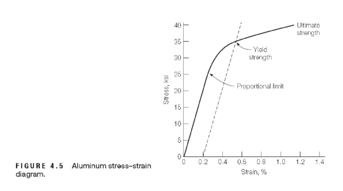
Referring to Figure 4.5, determine approximate values of the following:
a. modulus of elasticity
b. proportional limit
c. yield strength at a strain offset of 0.002
d. tangential modulus at a stress of 33 ksi
e. secant modulus at a stress of 33 ksi
Expert Solution & Answer
Want to see the full answer?
Check out a sample textbook solution
Students have asked these similar questions
1. Given the data, plot the stress-strain diagram
2. Determine the proportional limit
3. Determine the modulus of elasticity
A tension test performed on a metal specimen to fracture produced the stress– strain relationship shown in Figure P1.14. Graphically determine the following (show units and all work): a. Modulus of elasticity within the linear portion. b. Yield stress at an offset strain of 0.002 m/m. c. Yield stress at an extension strain of 0.005 m/m. d. Secant modulus at a stress of 525 MPa. e. Tangent modulus at a stress of 525 MPa.
The information in the photo attached shows elastic properties of a human tibula bone. If you were to take a small cuboidal cross section of the tibula bone and apply the ultimate shear stress, what would be the resulting strain?
(a) 1.0 %
(b) 6.7 %
(c) 10 %
(d) 15 %
(e) None of the above.
Chapter 4 Solutions
Materials for Civil and Construction Engineers (4th Edition)
Ch. 4 - Name the two primary factors that make aluminum an...Ch. 4 - Prob. 4.2QPCh. 4 - An aluminum alloy specimen with a radius of 0.28...Ch. 4 - An aluminum alloy bar with a radius of 7 mm was...Ch. 4 - Decode the characteristics of a 6063 T831...Ch. 4 - A round aluminum alloy bar with a 0.6 in. diameter...Ch. 4 - An aluminum alloy bar with a rectangular cross...Ch. 4 - A round aluminum alloy bar with a 0.25-in....Ch. 4 - An aluminum alloy rod has a circular cross section...Ch. 4 - An aluminum alloy cylinder with a diameter of 3...
Ch. 4 - A 3003-H14 aluminum alloy rod with 0.5 in....Ch. 4 - The stressstrain relation of an aluminum alloy bar...Ch. 4 - An aluminum specimen originally 300 mm long is...Ch. 4 - A tension stress of 40 ksi was applied on a 12-in....Ch. 4 - A tension test was performed on an aluminum alloy...Ch. 4 - In Problem 4.15, plot the stressstrain...Ch. 4 - Referring to Figure 4.5, determine approximate...Ch. 4 - Prob. 4.18QPCh. 4 - A tensile stress is applied along the long axis of...Ch. 4 - A cylindrical aluminum alloy rod with a 0.5 in....Ch. 4 - Prob. 4.21QPCh. 4 - Discuss galvanic corrosion of aluminum. How can...
Knowledge Booster


Learn more about
Need a deep-dive on the concept behind this application? Look no further. Learn more about this topic, civil-engineering and related others by exploring similar questions and additional content below.Similar questions
- The data in Table 1.5.3 were obtained from a tensile test of a metal specimen with a rectangular cross section of 0.2011in.2 in area and a gage length (the length over which the elongation is measured) of 2.000 inches. The specimen was not loaded to failure. a. Generate a table of stress and strain values. b. Plot these values and draw a best-fit line to obtain a stress-strain curve. c. Determine the modulus of elasticity from the slope of the linear portion of the curve. d. Estimate the value of the proportional limit. e. Use the 0.2 offset method to determine the yield stress.arrow_forwardA tension test performed on a metal specimen to fracture produced the stress-strain relationship shown in Figure. Graphically determine the following (show units and all work):a. Modulus of elasticity within the linear portion.b. Yield stress at an offset strain of 0.002 in./in.c. Yield stress at an extension strain of 0.005 in/in.d. Secant modulus at a stress of 62 ksi.e. Tangent modulus at a stress of 65 ksi.arrow_forward) Consider a cylindrical specimen of a steel alloy 10.0 mm in diameter and 75 mm long that is pulled in tension. (a) Determine its elongation when a load of 20,000 N is applied. (b) What is the modulus of elasticity? (c) What is the strength at a strain offset of 0.002? (d) What is the tensile strength?arrow_forward
- The data shown in the table were obtained from a tensile test of a metal specimen with a rectangular cross-section of 0.2 in.? in area and a gage length (the length over which the elongation is measured) of 2.000 inches. a. Generate a table of stress and strain values. b. Plot these values and draw a best-fit line to obtain a stress-strain curve. c. Determine the modulus of elasticity from the slope of the linear portion of the curve. d. Estimate the value of the proportional limit. e. Use the 0.2% offset method to determine the yield stress.arrow_forwardA tensile force of 20 kN is applied to a specimen with a gage length of 50mm. It is then noted that the distance between the gage marks became 50.122mm. a,) What is the modulus of elasticity of the specimen if its diameter is 10mm? b.) What is the axial stress of the specimen?Note: Please show detailed solutions with illustrations.arrow_forwardA part’s maximum Von Mises stress and materials are given below. Determine for each of these conditions whether the part is safe or not. Material: Steel, Von Mises Stress: 31000 psi, Static Loading, Ultimate Strength = 80000 psi Material: Polystyrene, Von Mises Stress: 42000 psi, Static Loading, Ultimate Strength = 7500 psi Material: Aluminum, Von Mises Stress: 62000 psi, Repeated Loading, Ultimate Strength = 30000 psi Please clearly show all calculations and reasoning in your computation.arrow_forward
- Find the poisson's ratio for a given material if the modulus of elasticity is 100 GN/m2 and it's modulus of elasticity in shear is 40 GPa.arrow_forwardA tensile test was performed on a metal specimen having a circular cross section with a diameter of 0.510 inch. For each increment of load applied, the strain was directly determined by means of a strain gage attached to the specimen. The results are shown in Table 1.1.a. Prepare a table of stress and strainb. Plot these data to obtain a stress-strain curve. Do not connect the data points; draw a best-fit straight line through them.c. Determine the modulus of elasticity as the slope of the best-fit lineLoad (Ib)Strain × 106 (in./in.)0025037.150070.31000129.11500230.12000259.42500372.43000457.73500586.5arrow_forwardThe plates in the figure below are each 3 inches by 0.5 inches in cross section. If the hole in each plate is 13/16 in diameter and the load p is 20 kips, determine the average tensile stress in the plate.arrow_forward
- 50% Due to loading, the plate is deformed into the dashed shape shown in the figure. Assume a = 32 in., b= 40 in., δ1= 0.225 in., δ2= 0.075 in. Determine the average normal strain along the side AB? Determine the average shear strain in the plate at A relative to the horizontal and vertical axes?arrow_forwardThe stress distribution on a structure is given by s=2x^(2)+4x-30 where s is stress in pounds per square inch and x is the distance in feet from a reference point. At what distance is the stress equal to 0 ?arrow_forwardThe results of a tensile test are shown in Table 1.5.2. The test was performed on a metal specimen with a circular cross section. The diameter was 3⁄8 inch and the gage length (the length over which the elongation is measured) was 2 inches. a. Use the data in Table 1.5.2 to produce a table of stress and strain values. b. Plot the stress–strain data and draw a best-fit curve. c. Compute the modulus of elasticity from the initial slope of the curve. d. Estimate the yield stressarrow_forward
arrow_back_ios
SEE MORE QUESTIONS
arrow_forward_ios
Recommended textbooks for you
 Steel Design (Activate Learning with these NEW ti...Civil EngineeringISBN:9781337094740Author:Segui, William T.Publisher:Cengage Learning
 Materials Science And Engineering PropertiesCivil EngineeringISBN:9781111988609Author:Charles GilmorePublisher:Cengage Learning
Steel Design (Activate Learning with these NEW ti...
Civil Engineering
ISBN:9781337094740
Author:Segui, William T.
Publisher:Cengage Learning
Materials Science And Engineering Properties
Civil Engineering
ISBN:9781111988609
Author:Charles Gilmore
Publisher:Cengage Learning
Material Properties 101; Author: Real Engineering;https://www.youtube.com/watch?v=BHZALtqAjeM;License: Standard YouTube License, CC-BY