
Videos
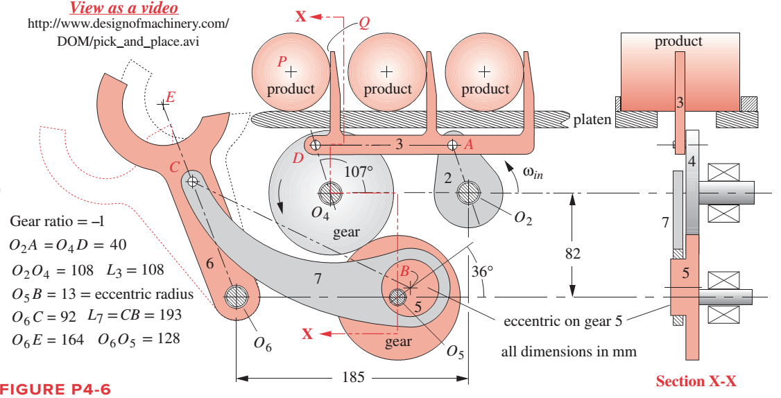
For one revolution of driving link 2 of the walking-beam indexing and pick-and-place
Want to see the full answer?
Check out a sample textbook solution
Chapter 4 Solutions
DESIGN OF MACHINERY (LL W/ CONNECT)
Additional Engineering Textbook Solutions
Thermodynamics: An Engineering Approach
Automotive Technology: Principles, Diagnosis, and Service (5th Edition)
Engineering Mechanics: Statics & Dynamics (14th Edition)
Introduction to Heat Transfer
Manufacturing Engineering & Technology
Fluid Mechanics: Fundamentals and Applications


- Given the vectors in Figure P1-2, use a scale of 1 inch = 10 units, and determine the following vectors: Figure P1-2 B=10 ; 270⁰ C=15 ; 210⁰ D=12,5 ; 315⁰ E= 7,5 ; 75⁰ F = 10 ; 215⁰ G= 15 ; 100⁰arrow_forwardRefer to the figure below for the mechanism. If link 2 rotates at a speed of 60 revolutions per minute in a counterclockwise direction , find the velocity, using resolution and composition method of: A point connecting link 2 to link 3 A point at the center of link 2 A point at the center of link 3 Of the slider Also, locate all the instantaneous centers.arrow_forwardEvaluate the 3-DOF wrist as shown in Figure 2, use the conventional method to determine 1. Linear velocity and 2. Angular velocity NOTE: for JOINT 3 ( 03 ) only Connected to robot Figure 2: Wrist assembly The known position and orientation of the end of the arm point is. [-C,S2C3 + S1S3 C;S2S3 +S1C3 |-S;S2C3 – C,S3 S,S2S3 + C,C3 -C2S3 C,C2 S,C2 S2 °T3=°T;'T2?T3= C2C3 [G 0 S, 0 S, 0 -G 0 °T 1 0 0 1 -S2 0 C, 0° C2 0 S, 0 'T2 1 1 [C3 -S3 0 07 S3 C3 0 0 2T3= 1 0 0 0 1 00010 IIarrow_forward
- Crack AB of a slider crack mechanism shown in Figure 2 rotate at a constant speed of 300 rpm in clockwise direction. The connecting rod BC has a length of 1 m and incline at 45o to vertically positioned piston C. No angle or length for AB is given in the original question, thus I assume the angle is 70o because of the rough drawing I did here. Draw the displacement diagram of the mechanism shown in Figure 2 to scale. Use a vector diagram to determine the velocity of the piston C and connecting rod BC. Calculate the acceleration of piston C and the angular acceleration of connecting rod BC.arrow_forwardCompute the position and orientation of the tool point P from the given D-H table for the displacement variable e1-90° e2-90° and e3=90⁰ a1= 100 mm, a2= 100mm and a3 = 50mm Note: find the position and orientation using step by step procedure Figure 3 3-DOF (Industrial manipulator arm) Joint 0 d 1 01 0 2 02 3 03 0 0 Present the roll, pitch, yaw and displacement in x, y and z axis. use the composite transformation matrix [ce; -se,Cα; se; SÔ i-¹T₁ = 0 0 Sα₁ 0 CÔ Ca; co,ca; a a1 a2 az s0;Sα; se a | -90 0 0 Cα₁ 0 a;C0₁] –CĐ Sa, : aS0; a¡SO; d; 1arrow_forwardFor the Figure shown, draw the kinematic diagram and Using instantaneous center method locate all the instant centers of the mechanism.arrow_forward
- Refer to the figure below for the mechanism.If link 2 rotates at a speed of 60 revolutions per minute, find the velocity, using resolution and composition method of: A point connecting link 2 to link 3 A point at the center of link 2 A point at the center of link 3 Of the slider Also, locate all the instantaneous centers. Use counterclockwise direction.arrow_forwardRefer to the figure below for the mechanism. If link 2 rotates at a speed of 60 revolutions per minute, find the velocity, using resolution and composition method of: A point connecting link 2 to link 3 A point at the center of link 2 A point at the center of link 3 Of the slider Also, locate all the instantaneous centers. Use counterclockwise direction.arrow_forwardPlz answer this question Given the vectors in Figure P1-2 using a scale of 1 inch = 10 units, and determine the following vectors on the image below: Additional information A= 20 B= 270⁰ ; 10 C=210⁰ ; 15 D=315⁰; 12,5 E=75⁰ ; 7,5 F=215⁰ ; 10 G=100⁰ ; 15arrow_forward
- B3. SOLVE STEP BY STEP IN DIGITAL FORMAT A set of sprockets is constructed, as shown in Figure 1, so that the second and third rotate on a common axis. When the first rotates, it drives the second and this in turn drives the third. Let and be the numbers of revolutions per minute of the first, second, and third axes. dy du dy dy dtu Find www.du' dx' and, and verify that dr du Figure 1 |1cm axis 1 |- 4cm -| axis 2 axis 1: y rev per minute axis 2: u rev per minute axis 3: x rev per minute |1e| |- 3cm-|| axis 3arrow_forwardQUESTION 6 Select the type of this mechanism below: L2 02 L3 А L1 C L4 O Crank-rocker O Triple rocker O Crank-crank O Slider-crankarrow_forwardThe linkage in Figure P7-5b has 04A = O2A = 0.75 , AB = 1.5 , and AC = 1.2 in . The effective crank angle in the position shown is 77º and angle BAC = 30 ° . Find a3 , AA , AB , Ac for the position shown for m2 = 15 rad / sec and a2 = 10 rad / sec2 in the directions shown using an analytical method . ( Hint : Create an effective linkage for the position shown and analyze it as a pin - jointed fourbar . ) the linkage has a parallelogram form Assume rolling contact C 02 A 3 . B 02 02 Tarrow_forward
 Elements Of ElectromagneticsMechanical EngineeringISBN:9780190698614Author:Sadiku, Matthew N. O.Publisher:Oxford University Press
 Mechanics of Materials (10th Edition)Mechanical EngineeringISBN:9780134319650Author:Russell C. HibbelerPublisher:PEARSON
 Thermodynamics: An Engineering ApproachMechanical EngineeringISBN:9781259822674Author:Yunus A. Cengel Dr., Michael A. BolesPublisher:McGraw-Hill Education
 Control Systems EngineeringMechanical EngineeringISBN:9781118170519Author:Norman S. NisePublisher:WILEY
 Mechanics of Materials (MindTap Course List)Mechanical EngineeringISBN:9781337093347Author:Barry J. Goodno, James M. GerePublisher:Cengage Learning
 Engineering Mechanics: StaticsMechanical EngineeringISBN:9781118807330Author:James L. Meriam, L. G. Kraige, J. N. BoltonPublisher:WILEY