![MindTap Engineering for Glover/Overbye/Sarma's Power System Analysis and Design, 6th Edition, [Instant Access], 1 term (6 months)](https://s3.amazonaws.com/compass-isbn-assets/textbook_empty_images/large_textbook_empty.svg)
Concept explainers
Videos
Figure 4.34 shows double-circuit conductors' relative positions in segment I of transposition of a completely transposed three-phase overhead transmission line. The inductance is given by
Where
With mean distances defined by equivalent spacings

And
Now consider a 345-kV, three-phase, double-circuit line with phase-conductor’s GMR of 0.0588 ft and the horizontal conductor configuration shown in Figure 4.35.
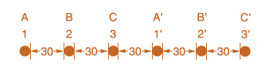
- Determine the inductance per meter per phase in Henries (H).
- Calculate the inductance of just one circuit and then divide by 2 to obtain the inductance of the double circuit.
Want to see the full answer?
Check out a sample textbook solution
Chapter 4 Solutions
MindTap Engineering for Glover/Overbye/Sarma's Power System Analysis and Design, 6th Edition, [Instant Access], 1 term (6 months)


- Conductor spacings, types, and sizes do have an impact on the series impedance and shunt admittance. True Falsearrow_forwardThe instantaneous power absorbed by the load in a single-phase ac circuit, for a general R LC load under sinusoidal-steady-state excitation. is (a) Nonzero constant (b) Zero (c) Containing double-frequency componentsarrow_forwardI need the answer as soon as possiblearrow_forward
- A single phase line has two parallel conductors 2m apart. The diameter of each conductor is 1.2 cm. Calculate the loop inductance/ phase/ kmoftheline.arrow_forwardA three-phase 50 Hz double circuit as shown below, assumed that the line is completely trasposed. The diameter of each conductor is 2.76 cm. Find the capacitance to neutral in uF/km b O O O O - -- 6m 6m 6m bm bmarrow_forward2.5 A 3-phase single circuit bundled conductor line with two sub-conductors per phase has horizontal spacing with 6.1 m between the centre lines of adjacent phases. The distance between the sub- conductors of each phase is 30.5 cm and each sub-conductor has a diameter of 2.54 cm. Find the inductance per phase per km. [0.988 mH]arrow_forward
- A three-phase 50 Hz double circuit as shown below, assumed that the line is completely trasposed. The diameter of each conductor is 2.76 cm. Find the capacitance to neutral in juF /km a b a b' --- 6m 6m 6m 6m 6marrow_forwardX₂=0.1 1 XL +03 Soto X₁ = 0.2 X = 0.1 X = 0.1 Above is the one-line diagram of a simple power system. Each generator is represented by an emf behind the subtransient reactance. All impedances are expressed in per unit on a common base. All resistances and shunt capacitance are neglected. The generators are operating on no load at their rated voltage with their emfs in phase. A symmetrical fault occurs at bus 1 through a fault impedance Z, =j0.08 per unit. a) Using Thevenin's Theorem, determine the impedance to the point of fault and the fault current in per unit. b) Find the bus voltages and line currents during the fault. 2 O otoarrow_forwardA parallel connection of a RL branch with a C branch is connected across a 100V AC mains. At first R = 10 ohms, L = 20mH and frequency of 1000rad / s, the current measured is 2.2361A at 89.44 leading power factor. A) Determine the initial capacitance. B) However, a fault occurs on the capacitor branch making its capacitance 20% lower and a resistance of 5 ohms is detected. If this faulty circuit is rerun but at a frequency of 500 rad / s, determine the new current that will flow through the circuitarrow_forward
- A parallel connection of a RL branch with a C branch is connected across a 100V AC mains. At first R = 10 ohms, L = 20mH and frequency of 1000rad / s, the current measured is 2.2361A at 89.44 leading power factor. A) Determine the initial capacitance. B) However, a fault occurs on the capacitor branch making its capacitance 20% lower and a resistance of 5 ohms is detected. If this faulty circuit is rerun but at a frequency of 500 rad / s, determine the new current that will flow through the circuit.arrow_forwardA 54 conductors/phase single phase line has a GMR of 15.9mm and a GMD of 2.3m. The axial length is 50m. Calculate the total inductance of this single phase line. 50 ΜΗ 65 ΜΗ Ο 70 μΗ 60 ΜΗ 55 ΜΗarrow_forwardParagraph Styles The power factor must be close to in the transmission lines will be reduced To insure that losses D(Ctrl) -arrow_forward
 Power System Analysis and Design (MindTap Course ...Electrical EngineeringISBN:9781305632134Author:J. Duncan Glover, Thomas Overbye, Mulukutla S. SarmaPublisher:Cengage Learning