
MASTERING ENGINEERING WITH PEARSON
10th Edition
ISBN: 9780134325262
Author: HIBBELER
Publisher: PEARSON
expand_more
expand_more
format_list_bulleted
Videos
Textbook Question
Chapter 4, Problem 4.2RP
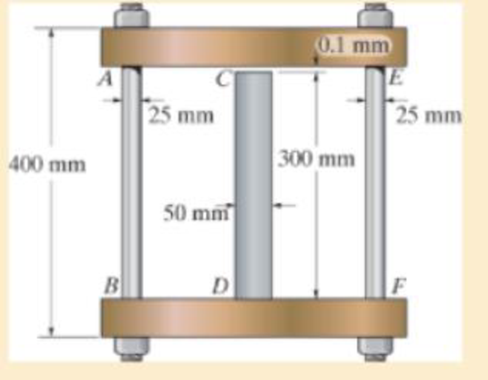
The assembly shown consists of two A992 steel bolts AB and EF and an 6061-T6 aluminum rod CD. When the temperature is at 30°C, the gap between the rod and rigid member AE is 0.1 mm. Determine the highest temperature to which the assembly can be raised without causing yielding either in the rod or the bolts Assume BF is also rigid
R4–1/2
Expert Solution & Answer
Want to see the full answer?
Check out a sample textbook solution
Students have asked these similar questions
The assembly consists of two A992 steel bolts AB and EF and an 6061-T6 aluminum rod CD. When the temperature is at 30° C, the gap between the rod and rigid member AE is 0.1 mm. Determine the normal stress developed in the bolts and the rod if the temperature rises to 130° C. Assume BF is also rigid.
The assembly shown consists of twoA36 steel bolts AB and EF and an 6061-T6aluminum rod CD. When the temperature is at30°C, the gap between the rod and rigid memberAE is 0.1 mm. Determine the highest temperatureto which the assembly can be raised withoutcausing yielding either in the rod or the bolts.Assume BF is also rigid.
The 0.35-inch-diameter cylinder is made from C83400 red brass and is placed in the device depicted below when temperature is T1 = 5 oF throughout. The two Am 1004-T-61 magnesium alloy carriage bolts each have a diameter of 0.10 inches and hold the cylinder snug with negligible force against the rigid jaws. Determine the maximum temperature (in oF) that the brass cylinder can be subjected to without causing yielding of any one of the materials. The end plates will not deform or fail.
Chapter 4 Solutions
MASTERING ENGINEERING WITH PEARSON
Ch. 4.2 - In each case, determine the internal normal force...Ch. 4.2 - Determine the internal normal force between...Ch. 4.2 - The post weighs 8kN/m. Determine the internal...Ch. 4.2 - The rod is subjected to an external axial force of...Ch. 4.2 - The rigid beam supports the load of 60 kN....Ch. 4.2 - The 20-mm-diameter A-36 steel rod is subjected to...Ch. 4.2 - Segments AB and CD of the assembly are solid...Ch. 4.2 - The 30-mm-diameter A992 steel rod is subjected to...Ch. 4.2 - If the 20-mm-diameter rod is made of A-36 steel...Ch. 4.2 - The 20-mm-diameter 2014-T6 aluminum rod is...
Ch. 4.2 - The 20-mm-diameter 2014-T6 aluminum rod is...Ch. 4.2 - The A992 steel rod is subjected to the loading...Ch. 4.2 - The copper shaft is subjected to the axial loads...Ch. 4.2 - The composite shaft, consisting of aluminum,...Ch. 4.2 - The composite shaft, consisting of aluminum,...Ch. 4.2 - The 2014-T6 aluminium rod has a diameter of 30 mm...Ch. 4.2 - The A-36 steel drill shaft of an oil well extends...Ch. 4.2 - The truss is made of three A-36 steel members,...Ch. 4.2 - The truss is made of three A-36 steel members,...Ch. 4.2 - The assembly consists of two 10-mm diameter red...Ch. 4.2 - The assembly consists of two 10-mm diameter red...Ch. 4.2 - The load is supported by the four 304 stainless...Ch. 4.2 - The load is supported by the four 304 stainless...Ch. 4.2 - The rigid bar is supported by the pin-connected...Ch. 4.2 - The post is made of Douglas fir and has a diameter...Ch. 4.2 - The post is made of Douglas fir and has a diameter...Ch. 4.2 - The coupling rod is subjected to a force of 5 kip....Ch. 4.2 - The pipe is stuck in the ground so that when it is...Ch. 4.2 - The is made of three pin-connected A992 steel...Ch. 4.2 - The linkage is made of three pin connected A992...Ch. 4.2 - The assembly consists of three titanium...Ch. 4.2 - The rigid beam is supported at its ends by two...Ch. 4.2 - The rigid beam is supported at its ends by two...Ch. 4.2 - The steel bar has the original dimensions shown in...Ch. 4.2 - Determine the relative displacement of one end of...Ch. 4.2 - The assembly consists of two rigid bars that are...Ch. 4.2 - The truss consists of three members, each made...Ch. 4.2 - Solve Prob. 426 when the load P acts vertically...Ch. 4.2 - The observation cage C has a weight of 250 kip and...Ch. 4.2 - The steel bar has the original dimensions shown in...Ch. 4.2 - The ball is truncated at its ends and is used to...Ch. 4.5 - The column is constructed from high-strength...Ch. 4.5 - The column is constructed from high-strength...Ch. 4.5 - The A-36 steel pipe has a 6061-T6 aluminum core....Ch. 4.5 - If column AB is made from high strength precast...Ch. 4.5 - If column AB is made from high strength precast...Ch. 4.5 - Determine the support reactions at the rigid...Ch. 4.5 - If the supports at A and C are flexible and have a...Ch. 4.5 - The load of 2000 lb is to be supported by the two...Ch. 4.5 - The load of 2000 lb is to be supported by the two...Ch. 4.5 - The A-36 steel pipe has an outer radius of 20 mm...Ch. 4.5 - The 10-mm-diameter steel bolt is surrounded by a...Ch. 4.5 - The 10-mm-diameter steel bolt is surrounded by a...Ch. 4.5 - The assembly consists of two red brass C83400...Ch. 4.5 - The rigid beam is supported by the three suspender...Ch. 4.5 - The bolt AB has a diameter of 20 mm and passes...Ch. 4.5 - If the gap between C and the rigid wall at D is...Ch. 4.5 - The support consists of a solid red brass C83400...Ch. 4.5 - If there are n fibers, each having a...Ch. 4.5 - The rigid bar is pinned at A and supported by two...Ch. 4.5 - The rigid bar is pinned at A and supported by two...Ch. 4.5 - The rigid bar is pinned at A and supported by two...Ch. 4.5 - The rigid bar is pinned at A and supported by two...Ch. 4.5 - The 2014-T6 aluminum rod AC is reinforced with the...Ch. 4.5 - The 2014-T6 aluminum rod AC is reinforced with the...Ch. 4.5 - The three suspender bars are made of A992 steel...Ch. 4.5 - The three A-36 steel wires each have a diameter of...Ch. 4.5 - The A-36 steel wires AB and AD each have a...Ch. 4.5 - The post is made from 6061-T6 aluminum and has a...Ch. 4.5 - The post is made from 6061-T6 aluminum and has a...Ch. 4.5 - The bracket is held to the wall using three A-36...Ch. 4.5 - The bracket is held to the wall using three A-36...Ch. 4.5 - If each of the posts has an unloaded length of 1 m...Ch. 4.5 - The rigid bar is supported by the two short white...Ch. 4.5 - The assembly consists of two posts AB and CD each...Ch. 4.5 - The assembly consists of two posts AB and CD each...Ch. 4.5 - The assembly consists of two posts AB and CD each...Ch. 4.5 - The wheel is subjected to a force of 18 kN from...Ch. 4.6 - The C83400-red-brass rod AB and 2014-T6- aluminum...Ch. 4.6 - The assembly has the diameters and material...Ch. 4.6 - The rod is made of A992 steel and has a diameter...Ch. 4.6 - The two cylindrical rod segments are fixed to the...Ch. 4.6 - The two cylindrical rod segments are fixed to the...Ch. 4.6 - The pipe is made of A992 steel and is connected to...Ch. 4.6 - The bronze C86100 pipe has an inner radius of 0.5...Ch. 4.6 - The 40-ft-long A-36 steel rails on a train track...Ch. 4.6 - The device is used to measure a change in...Ch. 4.6 - The bar has a cross-sectional area A, length L,...Ch. 4.6 - When the temperature is at 30C, the A-36 steel...Ch. 4.6 - When the temperature is at 30C, the A-36 steel...Ch. 4.6 - When the temperature is at 30C, the A-36 steel...Ch. 4.6 - The 50-mm-diameter cylinder is made from Am...Ch. 4.6 - The 50-mm-diameter cylinder is made from Am...Ch. 4.6 - The wires AB and AC are made of steel, and wire AD...Ch. 4.6 - The cylinder CD of the assembly is heated from T1...Ch. 4.6 - The cylinder CD of the assembly is heated from T1=...Ch. 4.6 - The metal strap has a thickness t and width w and...Ch. 4.9 - Determine the maximum normal stress developed in...Ch. 4.9 - If the allowable normal stress for the bar is...Ch. 4.9 - The steel bar has the dimensions shown. Determine...Ch. 4.9 - The A-36 steel plate has a thickness of 12 mm. If...Ch. 4.9 - Determine the maximum axial force P that can be...Ch. 4.9 - Determine the maximum normal stress developed in...Ch. 4.9 - The member is to be made from a steel plate that...Ch. 4.9 - The resulting stress distribution along section AB...Ch. 4.9 - The resulting stress distribution along section AB...Ch. 4.9 - Prob. 4.96PCh. 4.9 - The weight is suspended from steel and aluminum...Ch. 4.9 - The bar has a cross-sectional area of 0.5 in2 and...Ch. 4.9 - The distributed loading is applied to the rigid...Ch. 4.9 - The distributed loading is applied to the rigid...Ch. 4.9 - The rigid lever arm is supported by two A-36 steel...Ch. 4.9 - The rigid lever arm is supported by two A-36 steel...Ch. 4.9 - The 300-kip weight is slowly set on the top of a...Ch. 4.9 - The rigid beam is supported by three 25-mm...Ch. 4.9 - The rigid beam is supported by three 25-mm...Ch. 4.9 - The rigid beam is supported by the three posts A,...Ch. 4.9 - The rigid beam is supported by the three posts A,...Ch. 4.9 - The bar having a diameter of 2 in. is fixed...Ch. 4.9 - Determine the elongation of the bar in Prob.4108...Ch. 4.9 - The rigid beam is supported by three A-36 steel...Ch. 4 - The assembly consists of two A992 steel bolts AB...Ch. 4 - The assembly shown consists of two A992 steel...Ch. 4 - The rods each have the same 25-mm diameter and...Ch. 4 - Two A992 steel pipes, each having a...Ch. 4 - The force P is applied to the bar, which is made...Ch. 4 - The 2014-T6 aluminum rod has a diameter of 0.5 in....Ch. 4 - The 2014-T6 aluminum rod has a diameter of 0.5 in....Ch. 4 - The rigid link is supported by a pin at A and two...Ch. 4 - The joint is made from three A992 steel plates...
Knowledge Booster


Learn more about
Need a deep-dive on the concept behind this application? Look no further. Learn more about this topic, mechanical-engineering and related others by exploring similar questions and additional content below.Similar questions
- The 50-mm-diameter cylinder is made from Am 1004-T61 magnesium and is placed in the clamp when the temperature is T1 = 20° C. If the 304-stainless-steel carriage bolts of the clamp each have a diameter of 10 mm, and they hold the cylinder snug with negligible force against the rigid jaws, determine the force in the cylinder when the temperature rises to T2 = 130°C.arrow_forwardAn A-36-steel hoop has an inner diameter of 23.99 in., a thickness of 0.25 in., and a width of 1 in. If it and the 24-in.-diameter A rigid cylinder has a temperature of 65° F, determine the temperature to which the hoop should be heated in order for it to just slip over the cylinder. What is the pressure the hoop exerts on the cylinder, and the tensile stress in the ring when it cools back down to 65° F?arrow_forwardA gap of 0.02 in. exists between the composite rod and the wall when the temperature is 75°F. Determine the temperature at which the normal stress in the aluminum rod will be equal to -9 ksi. The temperature of the aluminum rod is _____ °F.arrow_forward
- If the bolt length is 220 mmmm and the sleeve length is 200 mmmm, determine the tension in the bolt when a force of 50 kNkN is applied to the brackets. Express your answer to three significant figures and include appropriate units. Given: The bolt AB in (Figure 1) has a diameter of 21 mmmm and passes through a sleeve that has an inner diameter of 42 mmmm and an outer diameter of 52 mmmm. The bolt and sleeve are made of A-36 steel and are secured to the rigid brackets as shown.arrow_forwardThe inner ring A has an inner radius r1 and outer radius r2. The outer ring B has an inner radius r3 and an outer radius r4, and r2 7 r3. If the outer ring is heated and then fitted over the inner ring, determine the pressure between the two rings when ring B reaches the temperature of the inner ring. The material has a modulus of elasticity of E and a coefficient of thermal expansion of a.arrow_forwardThe bell-crank mechanism is in equilibrium for an applied load of F1 = 11 kN applied at A. Assume a = 250mm, b = 100mm, c = 90mm, and θ = 40°. Pin B is in a double-shear connection and has a diameter of 29 mm. The bell crank has a thickness of 31 mm. Determine the shear stress in pin B. Express your answer in MPa rounded to the nearest hundredths.arrow_forward
- The bell-crank mechanism is in equilibrium for an applied load of F1 = 11 kN applied at A. Assume a = 250mm, b = 100mm, c = 90mm, and θ = 40°. Pin B is in a double-shear connection and has a diameter of 29 mm. The bell crank has a thickness of 31 mm. Determine the shear stress in pin B. and the the bearing stress in the bell crank at B.arrow_forwardThe bell-crank mechanism is in equilibrium for an applied load of F1 = 17 kN applied at A. Assume a = 300mm, b = 190mm, c = 85mm, and θ = 50°. Pin B is in a double-shear connection and has a diameter of 30 mm. The bell crank has a thickness of 32 mm. Determine(a) the shear stress in pin B.(b) the bearing stress in the bell crank at B.arrow_forwardThe support consists of a solid red brass C83400 copper post surrounded by a 304 stainless steel tube. Before the load is applied the gap between these two parts is 1 mm. Given the dimensions shown, determine the greatest axialload that can be applied to the rigid cap A without causing yielding of any one of the materials.arrow_forward
- two steel plates are held together by two bolts. a)determine the required diameter of the bolts if the failure shear stress is 300MPa using a factor of safety of 2. b)using the answer from a, determine the steel plates thickness if the failure bearing stress of the steel is 350MPa using factor of safety as 1.5arrow_forwardThe pipe assembly shown is subjected to a force F = 400 N. The pipe has an inner diameter of 20 mm and an outer diameter of 30 mm. It is made of steel with Sy = 250 MPa. Determine the safety factor at point A using the maximum shear stress theory. Select one: a. NA = 1.843 b. NA = 3.224 c. NA = 2.580 d. NA = 4.299arrow_forwardThe d = 17-mm-diameter solid rod passes through a D = 22-mm-diameter hole in the support plate. When a load P is applied to the rod, the rod head rests on the support plate. The support plate has a thickness of b = 12 mm. The rod head has a diameter of a = 34 mm, and the head has a thickness of t = 10 mm. The shear stress in the rod head cannot exceed 145 MPa, the punching shear stress in the support plate cannot exceed 95 MPa, and the bearing stress between the rod head and the support plate cannot exceed 135 MPa. Determine the maximum value of Pmax that can be supported by the structure.arrow_forward
arrow_back_ios
SEE MORE QUESTIONS
arrow_forward_ios
Recommended textbooks for you
 Elements Of ElectromagneticsMechanical EngineeringISBN:9780190698614Author:Sadiku, Matthew N. O.Publisher:Oxford University Press
 Mechanics of Materials (10th Edition)Mechanical EngineeringISBN:9780134319650Author:Russell C. HibbelerPublisher:PEARSON
 Thermodynamics: An Engineering ApproachMechanical EngineeringISBN:9781259822674Author:Yunus A. Cengel Dr., Michael A. BolesPublisher:McGraw-Hill Education
 Control Systems EngineeringMechanical EngineeringISBN:9781118170519Author:Norman S. NisePublisher:WILEY
 Mechanics of Materials (MindTap Course List)Mechanical EngineeringISBN:9781337093347Author:Barry J. Goodno, James M. GerePublisher:Cengage Learning
 Engineering Mechanics: StaticsMechanical EngineeringISBN:9781118807330Author:James L. Meriam, L. G. Kraige, J. N. BoltonPublisher:WILEY
Elements Of Electromagnetics
Mechanical Engineering
ISBN:9780190698614
Author:Sadiku, Matthew N. O.
Publisher:Oxford University Press
Mechanics of Materials (10th Edition)
Mechanical Engineering
ISBN:9780134319650
Author:Russell C. Hibbeler
Publisher:PEARSON
Thermodynamics: An Engineering Approach
Mechanical Engineering
ISBN:9781259822674
Author:Yunus A. Cengel Dr., Michael A. Boles
Publisher:McGraw-Hill Education
Control Systems Engineering
Mechanical Engineering
ISBN:9781118170519
Author:Norman S. Nise
Publisher:WILEY
Mechanics of Materials (MindTap Course List)
Mechanical Engineering
ISBN:9781337093347
Author:Barry J. Goodno, James M. Gere
Publisher:Cengage Learning
Engineering Mechanics: Statics
Mechanical Engineering
ISBN:9781118807330
Author:James L. Meriam, L. G. Kraige, J. N. Bolton
Publisher:WILEY
An Introduction to Stress and Strain; Author: The Efficient Engineer;https://www.youtube.com/watch?v=aQf6Q8t1FQE;License: Standard YouTube License, CC-BY