
Concept explainers
Videos
Find the value of
Answer to Problem 43E
The value of
Explanation of Solution
Calculation:
The circuit diagram is redrawn as shown in Figure 1,
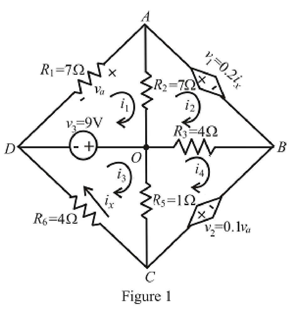
Refer to the redrawn Figure 1,
Apply KVL in the mesh
Here,
Apply KVL in the mesh
Here,
Apply KVL in the mesh
Here,
Apply KVL in the mesh
Here,
The expression for the voltage across
Here,
Refer to the redrawn Figure 1,
Substitute
Substitute
Substitute
Substitute
Rearrange the above equation for
Substitute
Substitute
Substitute
Substitute
Rearrange the equation (6), (10) and (11),
The equations so formed can be written in matrix form as,
Therefore, by Cramer’s rule,
The determinant of the coefficient matrix is as follows,
The 1st determinant is as follows,
The 2nd determinant is as follows,
The 3rd determinant is as follows,
Simplify for
Simplify for
Simplify for
The value of
Substitute
Conclusion:
Thus, the value of
Want to see more full solutions like this?
Chapter 4 Solutions
Engineering Circuit Analysis


- Using Thevenin’s theorem, find the equivalent circuit to the left of the terminals in the circuit of Fig. 4.30. Then find I.arrow_forward4.57 Obtain the Thevenin and Norton equivalent circuitsat terminals a-b for the circuit in Fig. 4.123.arrow_forwardGiven the circuit in Fig. 4.117, obtain the Norton equivalent as viewed from terminals:arrow_forward
- Find the Thevenin equivalent circuit of the circuit in Fig. 4.34 to the left of the terminals.arrow_forwardQuestion: 4.12 Determine vo in the circuit of Fig. 4.80 using the superposition principle.arrow_forwardDetermination Vth, Determination Rth, Thevenin equivalent circuit, Maximum Power.arrow_forward
- Determine Thevenin’s equivalent circuit which may be used to represent the network at the terminals AB.arrow_forward4.48 Determine the Norton equivalent at terminals a-b forthe circuit in Fig. 4.115.arrow_forwardUsing the superstition theorem, how would I prove the second images problem, given that #2 (voltage source was replaced with a short) measured 5 amps, and #4 (had the current source replaced with an open circuit) measured 1.6 amps?arrow_forward
- Number 4.29 Use source transformation to find correctly Vo in the circuit of Fig. 4.97.arrow_forwardUsing, necessarily, the superposition method, calculate the voltage that is applied on the terminals of the current source.arrow_forward4) Draw the Norton Equivalent of the circuit below.arrow_forward
 Introductory Circuit Analysis (13th Edition)Electrical EngineeringISBN:9780133923605Author:Robert L. BoylestadPublisher:PEARSON
 Delmar's Standard Textbook Of ElectricityElectrical EngineeringISBN:9781337900348Author:Stephen L. HermanPublisher:Cengage Learning
 Programmable Logic ControllersElectrical EngineeringISBN:9780073373843Author:Frank D. PetruzellaPublisher:McGraw-Hill Education
 Fundamentals of Electric CircuitsElectrical EngineeringISBN:9780078028229Author:Charles K Alexander, Matthew SadikuPublisher:McGraw-Hill Education
 Electric Circuits. (11th Edition)Electrical EngineeringISBN:9780134746968Author:James W. Nilsson, Susan RiedelPublisher:PEARSON
 Engineering ElectromagneticsElectrical EngineeringISBN:9780078028151Author:Hayt, William H. (william Hart), Jr, BUCK, John A.Publisher:Mcgraw-hill Education,