
Videos
A light-sensing circuit is in Fig. 4.90, including a resistor that changes value under illumination (photoresistor Rlight) and a variable resistor (potentiometer Rpot). The circuit is in the Wheatstone bridge configuration such that a “balanced” condition results in Vout = 0 for a defined value of incident light and a corresponding value for Rlight. (a) Derive an algebraic expression for Vout in terms of RS, R1, R2, Rlight, and Rpot. (b) Using the numerical values given in the circuit, calculate the value of Rpot required to balance the circuit at 500 lux, where Rlight = 200 Ω. (c) If the resistance of the photoresistor decreases by 2% for a light increase to 600 lux (and assuming the resistance change with light is linear), what will the light level be if you measure Vout = 150 mV?
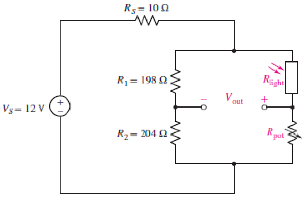
■ FIGURE 4.90
(a)
Write an algebraic expression for the output voltage
Explanation of Solution
Given data:
Refer to Figure 4.90 in the textbook.
Calculation:
The given circuit of Figure 4.90 is redrawn as shown in Figure 1.
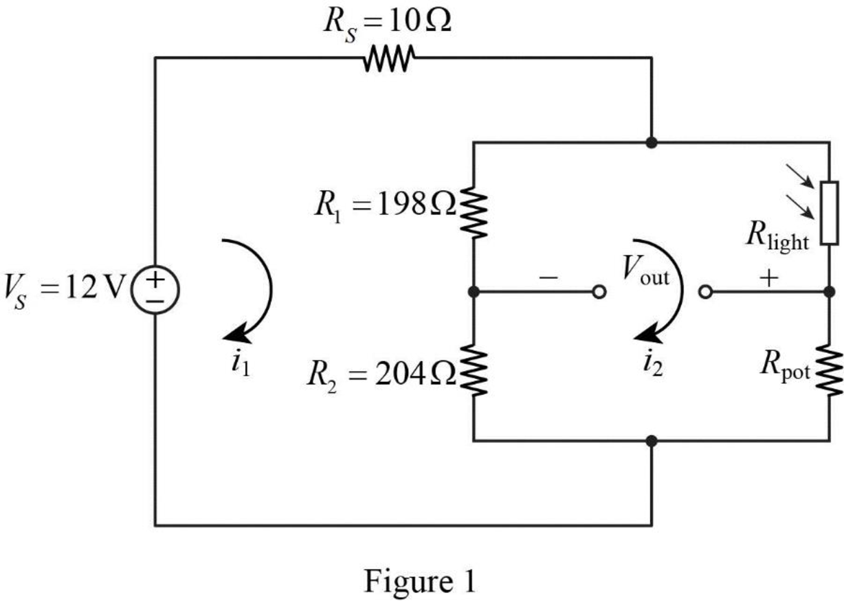
Apply Kirchhoff’s voltage law for the loop current
Apply Kirchhoff’s voltage law for the loop current
Rearrange the equation as follows,
Substitute equation (2) in equation (1).
Rearrange the equation as follows,
Substitute equation (3) in equation (2).
In Figure 1, the output voltage
Substitute equation (3) and (4) in equation (5).
Conclusion:
Thus, the output voltage
(b)
Calculate the value of variable resistor
Answer to Problem 74E
The value of variable resistor
Explanation of Solution
Given data:
Refer to Part (a).
The resistance
For balanced condition,
Calculation:
Refer to Part (a).
Substitute 0 for
Simplify the equation as follows,
Substitute
Conclusion:
Thus, the value of variable resistor
(c)
Find the light level if the resistance of the photoresistor decreases by 2% for a light increase to 600 lux with the measure of output voltage
Answer to Problem 74E
The light level is 760 lux if the resistance of the photoresistor decreases by 2% for a light increase to 600 lux with the measure of output voltage
Explanation of Solution
Given data:
Refer to Part (b).
The variable resistor
The output voltage
Calculation:
When the photoresistor resistance decreases by 2% with a light increase to 600 lux, then
Refer to Part (a), reduce the equation (6) as follows,
Substitute 12 V for
Reduce the equation as follows,
For a linear change, the light level is calculated as follows.
Conclusion:
Thus, the light level is 760 lux if the resistance of the photoresistor decreases by 2% for a light increase to 600 lux with the measure of output voltage
Want to see more full solutions like this?
Chapter 4 Solutions
Engineering Circuit Analysis
Additional Engineering Textbook Solutions
Introductory Circuit Analysis (13th Edition)
Programmable Logic Controllers
ELECTRICITY FOR TRADES (LOOSELEAF)
Basic Engineering Circuit Analysis
Electric Motors and Control Systems
Electric Circuits (10th Edition)


- the circuit shown in Fig.4, the current through 8Ω is *arrow_forwardThe Maximum Power Transfer Theorem is an extremely useful method of analysis. circuits, defining the condition under which the maximum power is transferred from the source to the charge" . Relating to the statement, consider that a linear circuit was simplified using Norton's Theorem. Your structure can be represented according to the diagram below. In this way, determine the maximum power transferred by him.arrow_forwardreport.The report should cover the followings1. Name of the experiment2. Objective3. Required Components and Equipments4. Experimental Setup (i.e., diagram of the circuit)J. Results and DiscussionsDraw a circuit diagram which will compare three 4 bit numbers. You haveMagnitude Comparators and 2:1 MUXs. plz attach the proteus filearrow_forward
- subject: discrete structures there may be several correct answers In which of the graphs on Fig.5, Fig.6, Fig.7 there exists Hamilton circuit?arrow_forwardConsider an approximate model of the epitaxial resistivity in a silicon power transistor:A pyramid structure with a square base has a resistor in every edge of the structure.The structure of the model is shown below. (a) Based on the description above, draw the relevant structure and include relevant resistors in your diagram. (b) Suppose the value of all resistors is R Ω, calculate the total resistance viewing from any of the a-x pairs. (c) Is the total resistance similar for all possible vertex pairs? Verify your statement above by including relevant calculation proof.arrow_forwardI have lab report attached below I need help with the following: A brief discussion of your conclusions, including how this experiment verifies (NOT PROVES) Ohm's Law. I do not understand the difference between verifying something and proving it, im hoping someone can help me out.arrow_forward
- In the node-voltage method, when a dependent voltage source connects two essential nodes, how can this situation be handled? A. The dependent source and its two ends are treated as a supernode for which a single KCL equation can be written. B. The two essential nodes are temporarily treated as having the same voltage. C. The dependent source is temporarily treated as an open circuit. D. The KCL equation is written for only one of the two essential nodes, and a KCL equation is written for the reference node. E. None of the provided options.arrow_forwardAs with the nodal analysis, the analysis of meshes for an electrical circuit is quite advantageous. This is because it also, to be developed, does not need a high number of equations. In practice, the main objective of this technique is to search for the intensities of called mesh currents. This is what can be done in the circuit presented below. Case the analysis of its meshes is carried out on it, what will be the current intensities found?arrow_forwardQ4- What are assumptions and claims for using the Head-mounted display. * please don't send the answer as a picturearrow_forward
- 4a- Please solve this question in detail. Thanksarrow_forwardExplain the principle of duality in system models and its applications in electrical circuit analysis.arrow_forwardQ2: Design series ohmmeter using PMMC of 100Ω internal resistance and 0.4ma full-scale deflection current. The required half-scale deflection is equal to 9kΩ.[use a battery of 9v]. Sketch the internal circuit diagram of the ohmmeter. Sketch also roughly the scale of the designed meter.arrow_forward
 Introductory Circuit Analysis (13th Edition)Electrical EngineeringISBN:9780133923605Author:Robert L. BoylestadPublisher:PEARSON
 Delmar's Standard Textbook Of ElectricityElectrical EngineeringISBN:9781337900348Author:Stephen L. HermanPublisher:Cengage Learning
 Programmable Logic ControllersElectrical EngineeringISBN:9780073373843Author:Frank D. PetruzellaPublisher:McGraw-Hill Education
 Fundamentals of Electric CircuitsElectrical EngineeringISBN:9780078028229Author:Charles K Alexander, Matthew SadikuPublisher:McGraw-Hill Education
 Electric Circuits. (11th Edition)Electrical EngineeringISBN:9780134746968Author:James W. Nilsson, Susan RiedelPublisher:PEARSON
 Engineering ElectromagneticsElectrical EngineeringISBN:9780078028151Author:Hayt, William H. (william Hart), Jr, BUCK, John A.Publisher:Mcgraw-hill Education,