
Videos
a.
The support reaction at point A and C and plot the shear, moment, and axial force diagram.
Answer to Problem 4.5.39P

Explanation of Solution
Given: .
The given figure.
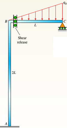
AB column and BC beam forms the plane frame that carries a load that is distributed in the triangular shape. At C there is roller support and support A is fixed. Below the B joint there is a moment release at column AB
Concept Used:
Vertical force equilibrium is given as,
Horizontal force equilibrium is given as,
Calculation: .
Vertical force equilibrium is given as,
Horizontal force equilibrium is given as,
At the top of the moment release the moment is given as,
In equation (1),
Below B there is moment release at point A,
At x the shear force is given and equated to 0,
At point x bending moment is maximum,
Axial force critical values
Shear force critical values
Moment critical values
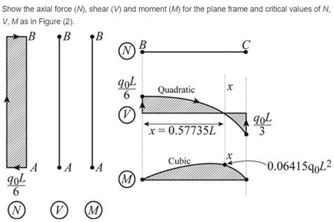
Conclusion: .
Thus, the support reaction at point A and C and plot the shear, moment and axial force diagram.
b.
For the load that is parabolic, lateral acts to the right added to AB column and part (a) is repeated.
Answer to Problem 4.5.39P
Explanation of Solution
Given: .
The given figure:.
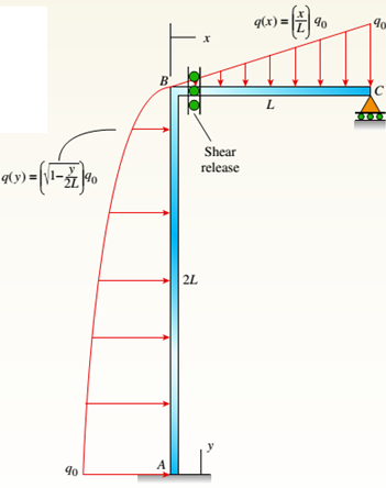
AB column and BC beam forms the plane frame that carries a load that is distributed in the triangular shape. At C there is roller support and support A is fixed. Below the B joint, there is a moment release at column AB.
Concept Used:
Vertical force equilibrium is given as,
Horizontal force equilibrium is given as,
Calculation: .
With the equilibrium force being vertical,
Moment at point B above moment release,
In (2) substitute
With the equilibrium force being horizontal,
As left of x axis is negative,
At A moment below the moment release,
At x shear force is calculated and equated to 0,
At x bending moment is calculated
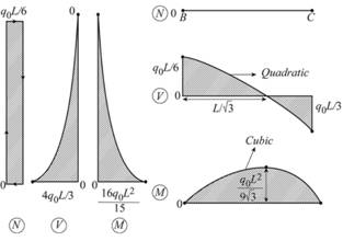
For plane frame and critical values of N, V, M, the axial, shear and moment is given.

Axial force critical values
Shear force critical values in beam
Shear force critical values in column
Moment critical values in beam
Moment critical values in column
Conclusion: .
Thus, for the load that is parabolic lateral acts to the right added to AB column and part (a) is repeated.
Want to see more full solutions like this?
Chapter 4 Solutions
Mechanics of Materials (MindTap Course List)


- Please solve step by step i want to understandarrow_forwardEstimate the mass transfer coefficient kc for benzoic acid dissolving into water at25 °C. Water flows at 0.15 m/s past the following solid benzoic acid geometries: Flowing parallel to a flat plate 0.175 m in length Flowing through a packed bed of spheres 8.0 mm in diameter, with ε = 0.40 You may assume a dilute solution.arrow_forwardA large volume of pure gas B at 2 atm pressure is flowing over a piece of blotting paper from which pure A is vaporizing. Liquid A completely wets the surface of the paper, so the partial pressure of A at the surface is the vapor pressure at 298 K, which is 0.20 atm. The ky has been estimated to be 6.78x10⁵ kmol/m².s.mole fraction. Calculate NA (the vaporization flux) and the value of ky and KG.arrow_forward
- Consider the bar-spring assemblage given in Figure 2 below. Assume that an additional external force F2x = -25kN is exerted. 1. Reproduce Figure 2 of the bar-spring assemblage to reflect the additional external force exerted 2. Using the direct stiffness method determine the following: a) Pertinent nodal displacements b) Reaction forces c) Forces in each element [2] [26] [6] [12] Hummel in 0.75 m E=1.0 × 10¹¹ N 3 50,000 N m² 4 A = 18 × 10-4 m² k = 100 KN kN 0.75 m Figure 2 NB: PLEASE CLEARLY SHOW YOUR WORKarrow_forwardConsider the spring assemblage shown in Figure 1. Assuming the rigid vertical bars at nodes 2 and 3 connecting the springs remain vertical; furthermore, consider that additional external forces are exerted including the forces F2x = -500N along element 1-2, F2x 250N along element 2-4 and F3x = 250N along element 3-4. = 1. Reproduce Figure 1 of the spring assemblage which reflects the additional external forces exerted 2. Using the direct stiffness method determine the following: a) Pertinent Nodal displacements b) Reaction forces c) Forces in each element NOTE: Element stiffnesses are given in N/mm [3] [25] [6] [20] 1 300 w 400 500 w w 300 w wwww 1000 N 13 400 2 Figure 1 NB: PLEASE CLEARLY SHOW YOUR WORKarrow_forward3. Өз ROA b RAO 02 04 a Ro₁₂ d R0402 link 1, RAO2 = link 2, Ro4A = link 3 = R2 = 3 in, R3 = 6 in, R₁ = 5 in, O2 =60°, and W2= 10 rad/sec ccw. For the 3Bar Inverted Crank Slider shown, 1. What are the position and velocity vector loop equations? 2. Determine the position equations and solve for 03. 3. Using the algebraic velocity equation method solve for wз and b, Do not forget units. The Polar-Cartesian Method will not be acceptedarrow_forward
- Please solve step by step i want to understandarrow_forwardPlease solve step step i want to understandarrow_forwardThe bar is subject to a force P as shown. Compute the 2D stresses at points H and K (Ihave used super-script H and K for these points). Assume that at the region of interest (i.e., at H, K), thecross-sectional area is A, polar moment of inertia J, and moment of inertia I. Your answers should be interms of P , L, d, A, J, and I.arrow_forward
- 3. Өз ROM R40% 02 a R0,0₂ d b R0402 link 1, RAO2 = link 2, Ro4A = link 3 R2 = 3 in, R3 = 6 in, R₁ = 5 in, O2 =60°, and W210 rad/sec ccw. For the 3Bar Inverted Crank Slider shown, 1. What are the position and velocity vector loop equations? 2. Determine the position equations and solve for 03. 3. Using the algebraic velocity equation method solve for w3 and b, Do not forget units. The Polar-Cartesian Method will not be acceptedarrow_forwardThe tube is subject to forces P and F, and torque T as shown. Compute the 2D stresses at points H and K (Ihave used super-script H and K for these points). Assume that at the region of interest (i.e., at H, K), thecross-sectional area is A, polar moment of inertia J, and moment of inertia I. Your answers should be interms of P , L, d, A, J, and I.arrow_forward1. The gear train in the following figure has a Diametrical Pitch of 8 teeth/inch with input power to the pinion of 20hp. a. Determine the gear sets. b. Determine the teeth of each gear. C. Determine the output angular velocity and direction of gear 7. d. Determine the torque on the pinion. e. Determine the output torque of gear 7. 15" D 9" D 5 7" D w2 120 rev/min 7 30" D 9" D 16" Darrow_forward
 Elements Of ElectromagneticsMechanical EngineeringISBN:9780190698614Author:Sadiku, Matthew N. O.Publisher:Oxford University Press
 Mechanics of Materials (10th Edition)Mechanical EngineeringISBN:9780134319650Author:Russell C. HibbelerPublisher:PEARSON
 Thermodynamics: An Engineering ApproachMechanical EngineeringISBN:9781259822674Author:Yunus A. Cengel Dr., Michael A. BolesPublisher:McGraw-Hill Education
 Control Systems EngineeringMechanical EngineeringISBN:9781118170519Author:Norman S. NisePublisher:WILEY
 Mechanics of Materials (MindTap Course List)Mechanical EngineeringISBN:9781337093347Author:Barry J. Goodno, James M. GerePublisher:Cengage Learning
 Engineering Mechanics: StaticsMechanical EngineeringISBN:9781118807330Author:James L. Meriam, L. G. Kraige, J. N. BoltonPublisher:WILEY