SYSTEM DYNAMICS CONNECT
3rd Edition
ISBN: 9781264201730
Author: Palm
Publisher: MCG CUSTOM
bartleby

Concept explainers

bartleby

Videos

Question
Book Icon
Chapter 4, Problem 4.68P
To determine

Whether the equation of motion of the pendulum and the system is stable, neutrally stable or unstable.

Expert Solution & Answer
Check Mark

Answer to Problem 4.68P

θ¨+22L(kL12mLg)=0 and the system is neutrally stable.

Explanation of Solution

Given:

A spring with stiffness k, and a damper with damping coefficient c, are attached to a pendulum of mass, m.

Concept used:

For an objects’ planar motion which rotates only about an axis perpendicular to the plane, the equation of motion can be written down using Newton’s Second Law.

Equation of Motion: Ioω˙=Mo

Where Io = Mass moment of Inertia of the body about point O.

ω = Angular velocity of the mass about an axis through a point O.

Mo = Sum of the moments applied to the body about the point O.

Let the angular displacement be θ.

The angular velocity, ω=dθdt=θ˙

ω˙=dωdt=d2θdt2=θ¨

Hence, the equation of motion of this object can be rewritten by substituting, ω˙=θ¨:

Ioθ¨=Mo

To find the equation of motion, the required unknowns are Io and Mo.

The mass moment of Inertia, I about a specified reference axis is given as:

I=r2dm

Where r = distance from the reference axis to mass element

Mass moment of Inertia of a rotating pendulum = r2dm=mr2

In this question, the distance from the reference axis to the mass element, r = L. Substituting this to the above equation gives:

Io=mL2

Mo = Sum of the moments applied to the body about the point O.

Moments = Perpendicular Force × Distance from the Pivot.

In this question, the pivot is point O.

Total moments about O = Moments of mass, m + Moments of spring element + Moments of the damper

Free body diagram of the system:
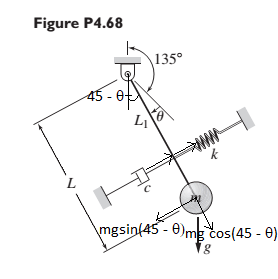
SYSTEM DYNAMICS CONNECT, Chapter 4, Problem 4.68P

Moments of mass, m:

The force mg can be resolved to two components, mgsin(45θ) and mgcos(45θ).

The force causing the moments will be mgsin(45θ) and its distance from the point O is L.

Moments = mgLsin(45θ) clockwise

Moments of the spring element:

Using the Hooke’s Law, a linear force-deflection model can be written, f=kx.

Where f = restoring force

x = compression or extension distance

k = Spring constant or stiffness

Here the extension distance, x=L1sin(45θ)

Hence the moments due to spring element = L1×k×L1sin(45θ)=kL12sin(45θ) anticlockwise.

Moments of the Damper:

The linear model for the force applied by the damper is:

f=cv

Where f = damping force

v = relative velocity

c = damping coefficient

Here the force, f=c×ddt(L1sin(45θ))

The distance between the pivot, O and the force applied = L1.

Hence Moments of the damper = L1×c×ddt(L1sin(45θ)) anticlockwise.

Taking clockwise to be positive and substitute the above expressions to the following equation,

Total moments about O = Moments of mass, m + Moments of spring element + Moments of the damper

Total moments = mgLsin(45θ)kL12sin(45θ)L1×c×ddt(L1sin(45θ))

Derivation of Equation of Motion:

Substitute Io=mL2 and Mo=mgLsin(45θ)kL12sin(45θ)L1×c×ddt(L1sin(45θ)) into the equation of motion Ioθ¨=Mo.

mL2θ¨=mgLsin(45θ)kL12sin(45θ)L12cddtsin(45θ)

Assuming θ is small, we can say sin(45θ)sin45 and the value sin45=22 can be substituted for sin(45θ).

mL2θ¨=mgL×22kL1222L12cddt22

The differentiation of a constant is 0, hence the moment due to the force applied by the damper becomes 0.

Simplifying the equation further:

mL2θ¨=mgL×22kL1222mL2θ¨mgL22+kL1222=0θ¨mgL22L2+kL1222mL2=0θ¨mgL22mL2+kL1222mL2=0θ¨g22L+kL1222mL2=0θ¨+22L(g+kL12mL)=0θ¨+22L(kL12mLg)=0

The equation of motion of the system is θ¨+22L(kL12mLg)=0. In this if kL12mL=g or kL12mL>g we can say that the system is neutrally stable.

When kL12mL=g, the roots obtained from the equation of motion will both be zero which indicates a neutral stability.

When kL12mL>g, the roots obtained from the equation of motion are imaginary and hence the system is neutrally stable.

Want to see more full solutions like this?

Subscribe now to access step-by-step solutions to millions of textbook problems written by subject matter experts!

Chapter 4 Solutions

SYSTEM DYNAMICS CONNECT

Ch. 4 - Plot the spring force felt by the mass shown in...Ch. 4 - Calculate the expression for the natural frequency...Ch. 4 - Prob. 4.13PCh. 4 - Obtain the expression for the natural frequency of...Ch. 4 - 4.15 A connecting rod having a mass of 3.6 kg is...Ch. 4 - Calculate the expression for the natural frequency...Ch. 4 - For each of the systems shown in Figure P4.17, the...Ch. 4 - The mass m in Figure P4.18 is attached to a rigid...Ch. 4 - In the pulley system shown in Figure P4.19, the...Ch. 4 - Prob. 4.20PCh. 4 - Prob. 4.21PCh. 4 - Prob. 4.22PCh. 4 - In Figure P4.23, assume that the cylinder rolls...Ch. 4 - In Figure P4.24 when x1=x2=0 the springs are at...Ch. 4 - 4.25 In Figure P4.25 model the three shafts as...Ch. 4 - In Figure P4.26 when 1=2=0 the spring is at its...Ch. 4 - Prob. 4.27PCh. 4 - For the system shown in Figure P4.28, suppose that...Ch. 4 - For the system shown in Figure P4.29, suppose that...Ch. 4 - Prob. 4.30PCh. 4 - For Figure P4.31, the equilibrium position...Ch. 4 - Prob. 4.32PCh. 4 - Prob. 4.33PCh. 4 - 4.34 For Figure P4.34, assume that the cylinder...Ch. 4 - Use the Rayleigh method to obtain an expression...Ch. 4 - Prob. 4.36PCh. 4 - 4.37 Determine the natural frequency of the system...Ch. 4 - Determine the natural frequency of the system...Ch. 4 - Use Rayleigh's method to calculate the expression...Ch. 4 - Prob. 4.40PCh. 4 - Prob. 4.41PCh. 4 - Prob. 4.42PCh. 4 - The vibration of a motor mounted on the end of a...Ch. 4 - Prob. 4.44PCh. 4 - Prob. 4.45PCh. 4 - A certain cantilever beam vibrates at a frequency...Ch. 4 - Prob. 4.47PCh. 4 - 4.48 The static deflection of a cantilever beam is...Ch. 4 - Figure P4.49 shows a winch supported by a...Ch. 4 - Prob. 4.50PCh. 4 - Prob. 4.51PCh. 4 - Prob. 4.52PCh. 4 - 4.53 In Figure P4.53 a motor supplies a torque T...Ch. 4 - Derive the equation of motion for the lever system...Ch. 4 - Prob. 4.55PCh. 4 - Figure P4.56a shows a Houdaille damper, which is a...Ch. 4 - 4.57 Refer to Figure P4.57. Determine the...Ch. 4 - For the system shown in Figure P4.58, obtain the...Ch. 4 - Find the transfer function ZsXs for the system...Ch. 4 - Prob. 4.60PCh. 4 - Find the transfer function YsXs for the system...Ch. 4 - Prob. 4.62PCh. 4 - 4.63 In the system shown in Figure P4.63, the...Ch. 4 - Prob. 4.64PCh. 4 - Figure P4.65 shows a rack-and-pinion gear in which...Ch. 4 - Figure P4.66 shows a drive train with a spur-gear...Ch. 4 - Prob. 4.67PCh. 4 - Prob. 4.68PCh. 4 - Prob. 4.69PCh. 4 - Figure P4.70 shows a quarter-car model that...Ch. 4 - Prob. 4.71PCh. 4 - 4.72 Derive the equation of motion for the system...Ch. 4 - A boxcar moving at 1.3 m/s hits the shock absorber...Ch. 4 - For the systems shown in Figure P4.74, assume that...Ch. 4 - Refer to Figure P4.75a, which shows a ship’s...Ch. 4 - In this problem, we make all the same assumptions...Ch. 4 - Refer to Figure P4.79a, which shows a water tank...Ch. 4 - The “sky crane” shown on the text cover was a...Ch. 4 - Prob. 4.81PCh. 4 - Prob. 4.82PCh. 4 - Suppose a mass in moving with a speed 1 becomes...Ch. 4 - Consider the system shown in Figure 4.6.3. Suppose...Ch. 4 - Prob. 4.86PCh. 4 - Figure P4.87 shows a mass m with an attached...Ch. 4 - Figure P4.88 represents a drop forging process....Ch. 4 - Refer to Figure P4.89. A mass m drops from a...Ch. 4 - Prob. 4.90PCh. 4 - (a) Obtain the equations of motion of the system...Ch. 4 - Refer to part (a) of Problem 4.90. Use MATLAB to...Ch. 4 - Refer to Problem 4.91. Use MATLAB to obtain the...Ch. 4 - 4.94 (a) Obtain the equations of motion of the...Ch. 4 - 4.95 (a) Obtain the equations of motion of the...
Knowledge Booster
Background pattern image
Mechanical Engineering
Learn more about
Need a deep-dive on the concept behind this application? Look no further. Learn more about this topic, mechanical-engineering and related others by exploring similar questions and additional content below.
Recommended textbooks for you
Text book image
Elements Of Electromagnetics
Mechanical Engineering
ISBN:9780190698614
Author:Sadiku, Matthew N. O.
Publisher:Oxford University Press
Text book image
Mechanics of Materials (10th Edition)
Mechanical Engineering
ISBN:9780134319650
Author:Russell C. Hibbeler
Publisher:PEARSON
Text book image
Thermodynamics: An Engineering Approach
Mechanical Engineering
ISBN:9781259822674
Author:Yunus A. Cengel Dr., Michael A. Boles
Publisher:McGraw-Hill Education
Text book image
Control Systems Engineering
Mechanical Engineering
ISBN:9781118170519
Author:Norman S. Nise
Publisher:WILEY
Text book image
Mechanics of Materials (MindTap Course List)
Mechanical Engineering
ISBN:9781337093347
Author:Barry J. Goodno, James M. Gere
Publisher:Cengage Learning
Text book image
Engineering Mechanics: Statics
Mechanical Engineering
ISBN:9781118807330
Author:James L. Meriam, L. G. Kraige, J. N. Bolton
Publisher:WILEY
Ch 2 - 2.2.2 Forced Undamped Oscillation; Author: Benjamin Drew;https://www.youtube.com/watch?v=6Tb7Rx-bCWE;License: Standard youtube license