
Videos
Verify numerical values for each nodal voltage in Exercise 14 by employing LTspice or a similar CAD tool. Submit a printout of an appropriately labeled schematic with the nodal voltages highlighted, along with your hand calculations.
Verify the solution obtained in Exercise 14 using LTspice.
Explanation of Solution
Calculation:
Refer to FIGURE 4.44 in the textbook.
Apply nodal analysis at node
Apply nodal analysis at node
Apply nodal analysis at node
Apply nodal analysis at node
Solve the equations by Cramer’s rule.
Find
Find
The value of
Find
The value of
Find
The value of
Find
The value of
Apply nodal analysis at node
Apply nodal analysis at node
Apply nodal analysis at node
Apply nodal analysis at node
Solve the equations by Cramer’s rule.
Find
Find
The value of
Find
The value of
Find
The value of
Find
The value of
Thus, the nodal voltages are,
| S. No | Node | Nodal voltage |
| 1 | 3.078 V | |
| 2 | –2.349 V | |
| 3 | 0.3109 V | |
| 4 | –0.3454 V | |
|
5 | 1.02 V | |
|
6 | 9.217 V | |
| 7 | 13.095 V | |
| 8 | 2.6768 V |
Draw the circuit diagram in LTspice as shown in Figure 1.
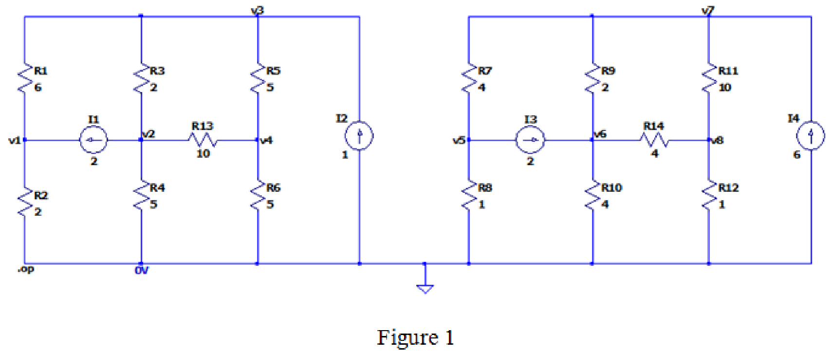
The output after simulating the LTspice circuit is,
--- Operating Point ---
V(v3): 0.310881 voltage
V(v1): 3.07772 voltage
V(v2): -2.34888 voltage
V(v4): -0.345423 voltage
V(v7): 13.0951 voltage
V(v5): 1.01901 voltage
V(v6): 9.21673 voltage
V(v8): 2.67681 voltage
I(I3): 2 device_current
I(I1): 2 device_current
I(I4): 6 device_current
I(I2): 1 device_current
I(R14): -1.63498 device_current
I(R13): 0.200345 device_current
I(R12): 2.67681 device_current
I(R11): 1.04183 device_current
I(R10): 2.30418 device_current
I(R9): 1.93916 device_current
I(R8): 1.01901 device_current
I(R7): 3.01901 device_current
I(R6): -0.0690846 device_current
I(R5): 0.131261 device_current
I(R4): -0.469775 device_current
I(R3): 1.32988 device_current
I(R2): 1.53886 device_current
I(R1): -0.46114 device_current
The both calculated and simulated values are approximately equal.
Conclusion:
Therefore, the solution is verified with the LTspice simulation.
Want to see more full solutions like this?
Chapter 4 Solutions
ENGINEERING CIRCUIT...(LL)>CUSTOM PKG.<


- Hello. Attached is a practice problem I am working on. I am super confused on how to get started and not sure how to complete the problem. Could you help me through it? Thank you. I appreciate your time.arrow_forwardHello Sir,Good Morning I have a question in my home work related mechatronics lesson. The following below is my question. Please advise thank you.arrow_forwardmpt3D1966098&cmid%3D11648 My Courses This course c. 11= 10 A, 12 = 5 A, V=50 V O d. 11 5 A, 12 = 2.5 A, V=25 V Question 5 For this circuit Is and V2 = Not yet R1 R2 R3 answered Marked out of 6.00 P Flag question V2 Is Vs R4 12 V Select one: O a. Is = 1 A, V2= 4 V O b. Is = 2 A, V2= 2V Oc. Is = 2 A, V2= 4 V O d. Is = 1 A, V2= 2 V Question 6 Use current division to find the currenti 120 flowing through the 120 resist Not yet answered Marked out of 28 7.00 +arrow_forward
- 9)The........and the ........are very similar a)engineer's scale rule and architect's scale rule b) engineer's scale rule and the desk ruler c) protractor and adjustable triangle ruler d)architect's scale rule and drafting triangle 10) Graphical abbreviations are used on electrical diagrams to illustrate the wiring between electrical devices and terminals. The electrical devices are either shown in block diagram form or using commonly defined symbols. a) true b) false [ i need both answer]arrow_forwardPLS ANSWER IN 30 MIN SIR SUBJECT (CONTROL ENGINEERING) PLS USE THIS MATRIX NUM SIR (AD 200107)arrow_forwardPROBLEM NUMBER ONE: The closed-loop transfer function of a negative unity feedback system is given by (s + 4)(s − 1) - T(s) = 55 +254 +25³ +4² +5+2 Determine the systems stability using the Routh Hurwitz Criterion for Stability. Depending on the case, use the following required method: Case 1: Apply the usual procedure of the Routh array. Case 2: Apply the Reciprocal of Roots and Reverse Coefficients Case 3: Apply Auxiliary Polynomialarrow_forward
- A. Discuss the importance of power electronics interfaces in microgrid installations B. With the aid of diagram describe DC microgrid C. With the aid of diagram describe AC microgridarrow_forwardDraw the resistor schematic symbol. What is the reason of the materials resistance in the circuit? What the international unit for resistance?arrow_forwardYou are working as an electrician in a large steel manufacturing plant, and you are in the process of doing preventive maintenance on a large DC generator. You have megged both the series and shunt field windings and found that each has over 10 M to ground. Your ohmmeter, however, indicates a resistance of 1.5 across terminals S1andS2. The ohmmeter indicates a resistance of 225 between terminals F1andF2. Are these readings normal for this type machine, or is there a likely problem? Explain your answer.arrow_forward
 Delmar's Standard Textbook Of ElectricityElectrical EngineeringISBN:9781337900348Author:Stephen L. HermanPublisher:Cengage Learning
 Electricity for Refrigeration, Heating, and Air C...Mechanical EngineeringISBN:9781337399128Author:Russell E. SmithPublisher:Cengage Learning
 Power System Analysis and Design (MindTap Course ...Electrical EngineeringISBN:9781305632134Author:J. Duncan Glover, Thomas Overbye, Mulukutla S. SarmaPublisher:Cengage Learning