
Logic gate:
- Logic gate is an electronic circuit that is used to take logical decisions based on the input.
- It contains one or more number of inputs and one output.
- The working of logic gate is based on the binary principle that has two states either logic 0 or logic 1.
- The output of logic gate is produced when it satisfies any of its logic conditions.
- The logic condition depends upon the type of the gates and the number of inputs.
- The primary logic gates include AND, OR and NOT and the combinations of these gates are used to implement any of the other logic gates.
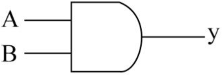
AND gate:
- The AND gate refers to a logic gate whose output will be HIGH only when all the inputs are HIGH.
- The output of AND gate will be LOW when any one of its input is LOW.
- The symbol to represent AND gate is given below:
- The truth table for AND gate is as follows:
| INPUT A | INPUT B | OUTPUT Y |
| 0 | 0 | 0 |
| 0 | 1 | 0 |
| 1 | 0 | 0 |
| 1 | 1 | 1 |
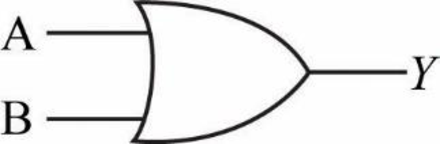
OR gate:
- The OR gate refers to a logic gate whose output will be HIGH when any one of its inputs are HIGH.
- The output of AND gate will be LOW when both the inputs are LOW.
- The symbol to represent OR gate is given below:
- The truth table for OR gate is as follows:
| INPUT A | INPUT B | OUTPUT Y |
| 0 | 0 | 0 |
| 0 | 1 | 1 |
| 1 | 0 | 1 |
| 1 | 1 | 1 |
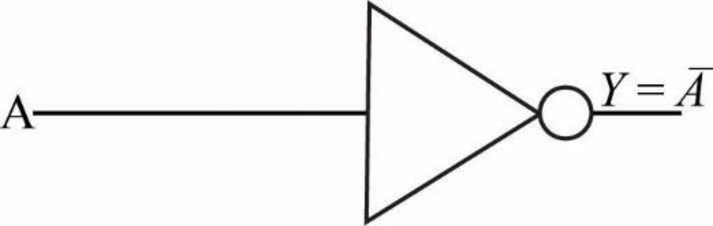
NOT gate:
- The NOT gate refers to a logic gate whose output will be HIGH when it’s input is LOW and whose output will be LOW when it’s input is HIGH.
- The symbol to represent NOT gate is given below:
- The truth table for NOT gate is as follows:
| INPUT A | OUTPUT Y |
| 0 | 1 |
| 1 | 0 |
Explanation of Solution
b.
Logic gate circuit:
The logic gate circuit for the given Boolean expression
Explanation:
In the above given logic gate circuit,
- The inputs “A” and “B” are connected to logic AND gate and the corresponding output will be (AB)
Explanation of Solution
c.
Logic gate circuit:
The logic gate circuit for the given Boolean expression
Explanation:
In the above given logic gate circuit,
- The inputs “A” and “B” are connected to logic OR gate and the corresponding output will be (A+B).
- The input “C” is connected to logic NOT gate and the corresponding output will be “
Explanation of Solution
d.
Logic gate circuit:
The logic gate circuit for the given Boolean expression
Explanation:
In the above given logic gate circuit,
- The inputs “C” and “D” are connected to logic AND gate and the corresponding output will be (CD).
- Now, the resultant along with other input “B” is connected to logic OR gate whose output will be
Explanation of Solution
e.
Logic gate circuit:
The logic gate circuit for the given Boolean expression
Explanation:
In the above given logic gate circuit,
- The input “A” is connected to logic NOT gate and the corresponding output will be “
Explanation of Solution
f.
Logic gate circuit:
The logic gate circuit for the given Boolean expression
Explanation:
In the above given logic gate circuit,
- The inputs “A”, “B” and “C” are connected to logic AND gate and the corresponding output will be (ABC).
- Now, the resultant along with the other input “D” is connected to logic OR gate whose output will be

Trending nowThis is a popular solution!

Chapter 4 Solutions
PROGRAMMABLE LOGIC PACKAGE

- 3. A COMBINATIONAL CIRCUIT IS DEFINED BY THE FOLLOWING THREE BOOLEAN FUNCTIONS. DESIGN THE CIRCUIT WITH A DECODER AND EXTERNAL GATES F1= X'Y'Z' + XZ F2= XY'Z' + X'Y F3= X'Y'Z + XYarrow_forwardDraw logic diagrams of the circuits that implement the original and simplified expressions in Problem ( x + y ) ′ ( x ′ + y ′ ) x ′ z ′ + xyz + xz ′ w ′ x ( z ′ + y ′ z ) + x ( w + w ′ yz )arrow_forwardWrite the Boolean equations and draw the logic diagram of the circuit whose outputs are defined by the following truth table: Table P2.27f 1 f 2 a b c1 1 0 0 00 1 0 0 11 0 0 1 01 1 0 1 11 0 1 0 00 1 1 0 11 0 1 1 1arrow_forward
- The following logic circuit has four inputs A, B, C, and D. Write the Boolean expression for X. Can we simplify it?arrow_forwardGiven the Boolean function: F = xy' + z'y'z + xyz e. Draw the logic diagram from the simplified expression and compare the total number of gates wilh the diagram of part (b).arrow_forwardConstruct a combinatorial circuit using inverters, OR gates, and AND gates that produces the output((¬p∨¬r)∧¬q)∨(¬p∧(q∨r))from input bits p,q, and r.arrow_forward
- Design a combinational circuit with four inputs— A, B, C, and D —and one output, F . F is to be equal to 1when A = 1, provided that B = 0, or when B = 1, provided that either C or D is also equal to 1. Otherwise,the output is to be equal to 0.1. Obtain the truth table of the circuit.2. Simplify the output function.3. Draw the logic diagram of the circuit, using NAND gates with a minimum number of ICs.4. Construct the circuit and test it for proper operation by verifying the given conditions.arrow_forwardDesign a logic circuit with input signal A, control input B, and outputs X and Y to operate as follows: When B = 1, output X will follow input A, and output Y will be 0. When B = 0, output X will be 0, and output Y will follow input A.arrow_forwardA 1bit 4 to 1 multiplexer, the 4 inputs of the multiplexer will be the output of another combinational circuit with A and B as an input:00 = 1bit Adder01 = 1bit Subtractor10 = 1bit Comparator (equals)11 = XOR • truth table• Boolean Expression• Logic Circuit Here is the truth table guide:arrow_forward
- The truth table for a Boolean expression is shown on figure1. A, B, C, D are inputs and Y is the output Write the Boolean expression on SOP form Y = f (A, B, C, D) Minimize the function using Karnaugh Map (K Map) Draw the minimized function using logic gatesarrow_forwardA majority circuit is a combinational circuit whose output is equal to 1 if the input variables have more 1’s than 0’s. The output is 0 otherwise.1. (a) Design a three-input majority circuit by finding the circuit’s truth table, Boolean equation, and a logic diagram.2. (b) Write and verify a HDL gate-level model of the circuit.arrow_forwardDevelop a digital circuit that only consists can be simplified to a circuit consisting of three NOT gates, two 2-input AND gate and one 2-input OR gate that works with the truth tablearrow_forward
 Database System ConceptsComputer ScienceISBN:9780078022159Author:Abraham Silberschatz Professor, Henry F. Korth, S. SudarshanPublisher:McGraw-Hill Education
 Starting Out with Python (4th Edition)Computer ScienceISBN:9780134444321Author:Tony GaddisPublisher:PEARSON
 Digital Fundamentals (11th Edition)Computer ScienceISBN:9780132737968Author:Thomas L. FloydPublisher:PEARSON
 C How to Program (8th Edition)Computer ScienceISBN:9780133976892Author:Paul J. Deitel, Harvey DeitelPublisher:PEARSON
 Database Systems: Design, Implementation, & Manag...Computer ScienceISBN:9781337627900Author:Carlos Coronel, Steven MorrisPublisher:Cengage Learning
 Programmable Logic ControllersComputer ScienceISBN:9780073373843Author:Frank D. PetruzellaPublisher:McGraw-Hill Education