
Understanding Motor Controls
4th Edition
ISBN: 9781337798686
Author: Stephen L. Herman
Publisher: Delmar Cengage Learning
expand_more
expand_more
format_list_bulleted
Videos
Textbook Question
Chapter 41, Problem 1RQ
To answer the following questions refer to the circuit in Figure 41–6.
The pressure switch is shown as:
- a. Normally open
- b. Normally closed
- c. Normally open held closed
- d. Normally closed held open
Expert Solution & Answer
To determine
The state of the pressure switch used in the circuit shown in Figure 41-6.
Explanation of Solution
Refer text book Figure 41-6.
The pressure switch shown in the circuit has its movable contact above the fixed contact. Hence, the pressure switch is normally closed and kept open for the circuitry purpose. This switch is called a “normally closed held open switch”. The schematic of normally closed held open pressure switch is shown in Figure 1 below:
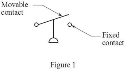
Thus, the correct answer is “option d. normally closed held open”.
Want to see more full solutions like this?
Subscribe now to access step-by-step solutions to millions of textbook problems written by subject matter experts!
Chapter 41 Solutions
Understanding Motor Controls
Ch. 41 - To answer the following questions refer to the...Ch. 41 - To answer the following questions refer to the...Ch. 41 - Prob. 3RQCh. 41 - To answer the following questions refer to the...Ch. 41 - To answer the following questions refer to the...Ch. 41 - Prob. 6RQCh. 41 - To answer the following questions refer to the...Ch. 41 - To answer the following questions refer to the...Ch. 41 - Prob. 9RQCh. 41 - Prob. 10RQ
Knowledge Booster


Learn more about
Need a deep-dive on the concept behind this application? Look no further. Learn more about this topic, mechanical-engineering and related others by exploring similar questions and additional content below.Similar questions
- To answer the following questions refer to the circuit in Figure 416. What is the purpose of the rotary switch connected after the pressure switch?arrow_forwardTo answer the following questions refer to the circuit shown in Figure 4110. Assume that the third speed push button is pressed and the motor starts in its first or lowest speed. After a delay of 3 seconds, the motor accelerates to its second speed, but never accelerates to its highest or third speed. Which of the following could cause this problem? a. CR coil is open. b. Coil 2TR is open. c. Coil 1TR is open. d. Coil 1S is open.arrow_forwardRefer to the circuit shown in Figure 16-11. Assume that the platform is located on the bottom floor. When the UP push button is pressed the pump motor does not start. Which of the following could not cause this problem? The contacts of limit switch LS1 are open. The contacts of limit switch LS2 are open. Motor starter coil M is open. The overload contact is open.arrow_forward
- Refer to the circuit shown in Figure 16-11. Assume that the platform is located on the lower floor. When the UP push button is pressed, the platform rises. When the platform reaches the upper floor, however, the pump does not turn off but continues to run until the overload relay opens the overload contacts. Which of the following could cause this problem? a. The solenoid valve opened when limit switch LS1 opened. b. The UP push button is shorted. c. Limit switch LS1 did not open its contacts. d. Limit switch LS2 contacts did not reclose when the platform began to rise.arrow_forwardRefer to the circuit shown in Figure 2614. When the START button is pressed, the control transformer fuse blows immediately. Which of the following could not cause this problem? a. Control relay coil CR is shorted. b. Starter coil 1M is shorted. c. Contactor coil S is shorted. d. Contactor coil 2M is shorted.arrow_forwardTo answer the following questions refer to the circuit shown in Figure 41–10. Assume that the third speed push button is pressed. Explain the sequence of operation for the circuit.arrow_forward
- To answer the following questions refer to the circuit in Figure 416. When the pressure switch closes, which starter will energize first, 1M or 2M? Explain your answer.arrow_forwardRefer to the circuit shown in Figure 25–5. Assume that timer TR1 is set for a delay of 10 seconds and timer TR2 is set for a delay of 5 seconds. When the START button is pressed, the motor starts. After 10 seconds the S1 contacts open and the motor continues to accelerate, but never reaches full speed. After a delay of about 30 seconds, the motor trips out on overload. Which of the following could cause this problem? TR1 coil is open. S2 coil is open. S1 coil is open. R coil is open.arrow_forwardRefer to the circuit shown in Figure 33–7. When the low speed push button is pressed, the motor begins to run in low speed. When the high speed push button is pressed, the motor stops running. Which of the following could cause this problem? The 1L contactor coil is open. H contactor coil is open. PR relay coil is open. The 2L contactor coil is open.arrow_forward
- Refer to the circuit shown in Figure 109. In this circuit the jog push button has again been connected incorrectly. The normally closed section of the button has been connected in series with the normally open run push button and the normally open section of the jog button is connecting in parallel with the holding contacts. Explain how this circuit operates.arrow_forwardRefer to the circuit shown in Figure 4221. Assume that the THIRD SPEED push button is pressed. The motor starts in second speed, skipping first speed. After 5 seconds, the motor accelerates to third speed. Which of the following could cause this problem? a. S1 contactor coil is open. b. CR1 contactor coil is open. c. TRl timer coil is open. d. S1 load contacts are shorted.arrow_forwardRefer to the circuit shown in Figure 108. In this circuit, the jog button has been connected incorrectly. The normally closed section has been connected in parallel with the run push button and the normally open section has been connected in series with the holding contacts. Explain how this circuit operates.arrow_forward
arrow_back_ios
SEE MORE QUESTIONS
arrow_forward_ios
Recommended textbooks for you
 Understanding Motor ControlsMechanical EngineeringISBN:9781337798686Author:Stephen L. HermanPublisher:Delmar Cengage Learning
Understanding Motor Controls
Mechanical Engineering
ISBN:9781337798686
Author:Stephen L. Herman
Publisher:Delmar Cengage Learning
Physics 33 - Fluid Statics (1 of 10) Pressure in a Fluid; Author: Michel van Biezen;https://www.youtube.com/watch?v=mzjlAla3H1Q;License: Standard YouTube License, CC-BY