
Videos
(a)
Find the residual stress at
(a)
Answer to Problem 92P
The residual stress is
Explanation of Solution
Given information:
The yield stress for the beam is
The Young’s modulus of steel is
Calculation:
Show the cross-section of the beam as shown in Figure 1.
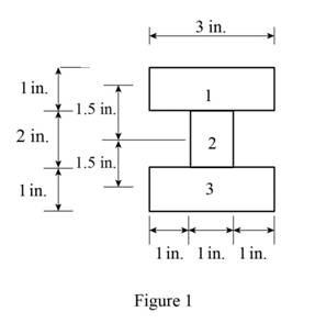
Refer to Figure 1.
Calculate the area of the cross section
Here, b is the width of the cross section and d is the depth of the cross section.
Calculate the area of the portion (1)
Substitute
Calculate the area of the portion (2)
Substitute
Calculate the moment of inertia
Calculate the moment of inertia of portion (1)
Substitute
Hence,
Calculate the moment of inertia of portion (2)
Substitute
Calculate the total moment of inertia
Substitute
Calculate the centroid (c) as shown below.
Substitute
Sketch the stress acting on the cross-section of the beam as shown in Figure 2.
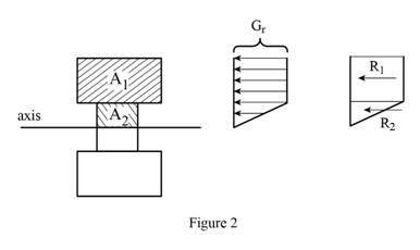
Refer Figure 2.
Calculate the area of the portion (2)
Substitute
Calculate the reaction applied to portion (1)
Substitute
Calculate the reaction applied to portion (2)
Substitute
Calculate the moment
Substitute
Calculate the stress
Substitute
Calculate the stress
Substitute
Calculate the residual stress at
Substitute
Calculate the residual stress at
Substitute
Sketch the stress distribution as shown in Figure 3.
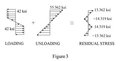
Hence, the residual stress is
(b)
Find the point where the residual stress is zero.
(b)
Answer to Problem 92P
The point where the residual stress is zero is
Explanation of Solution
Given information:
The yield stress for the beam is
The Young’s modulus for steel is
Calculation:
Consider that the residual stress is
Calculate the yield stress
Calculate the point where the residual stress is zero as shown below.
Substitute
Substitute
Therefore, the point where the residual stress is zero is
(c)
Find the radius of curvature corresponding to the permanent deformation of the bar.
(c)
Answer to Problem 92P
The radius of curvature is
Explanation of Solution
Given information:
The yield stress for the beam is
The Young’s modulus of steel is
Calculation:
Refer to part (a).
The residual stress
Calculate the radius of curvature
Calculate the point where the residual stress is zero as shown below.
Substitute
Therefore, the radius of curvature is
Want to see more full solutions like this?
Chapter 4 Solutions
MECHANICS OF MATERIAL (LL)


- The beam is made of four aluminium plates welded together as shown in Figure 1. Knowing that E = 65 GPa and neglecting the effect of the fillet. Determine the corresponding radius of curvature of the beam.arrow_forwardTwo cylindrical rods, one of steel and the other of brass, are joined at C and restrained by rigid supports at A and E. The steel rod has a length of 300 mm while the brass rod has a length of 200 mm. The diameters of the rods are shown in the figure below. A force of 60 kN is applied at point B of the steel segment. For the loading shown and knowing that modulus of elasticity values for steel and brass are respectively Es = 200 GPa and Eb = 105 GPa, determine a.) The reactions at A and E: RA and RE. b.) The deflection of point C from its original location. how to doarrow_forwardA solid 5/8-in. steel [E= 29,000 ksi] rod (1) supports beam AB. If the stress in the rod must not exceed 30 ksi and the maximum deformation in the rod must not exceed 0.25 in., determine the maximum load P that may be supported.arrow_forward
- A timber beam AB of length L and rectangular cross section carries a single concentrated load P at its midpoint C. (a) Show that the ratio Tm/ m of the maximum values of the shearing and normal stresses in the beam is equal to h/2L, where h and L are, respectively, the depth and the length of the beam. (b) Determine the depth h and the width b of the beam, knowing that L = 2 m, P = 40 kN, 7m = 960 kPa, and om = 12 MPa.arrow_forwardThe 70-mm-diameter steel rod ABC, and a brass rod CD of the same diameter, are joined at point C to form the 7.5-m long rod “ABCD”. E’s for the materials in the rod are shown in the picture below. For the loading shown, and neglecting the weight of the rod, determine: a) the deflection of point B b) the deflection of point C c) the deflection of point D d) the longitudinal stress in the middle of section AB e) the longitudinal stress in the middle of section BC f) the longitudinal stress in the middle of section CD a) all elemental stiffness matrices, b) the force matrix, and the c) assembly stiffness matrixarrow_forwardThe strut AB made from two bars (thickness of each bar = 0.50 in) is connected to a rectangular beam CD (b = 0.80 in x h = 7.5 in) at joint B. The beam carries a concentrated load of 2750 lb at the end joint D. (a) determine the minimum diameter of the bolt at B if the shearing stress in the bolt is not to exceed 14000 psi. (b) determine the minimum diameter of the bolt at B if the allowable bearing stress in the bar plate is 20000 psi. (Please provide detailed solution with FBD,thank you) ( a ) d = ? in ( b ) d = ? inarrow_forward
- A steel bar of 0.8 x 2.5-in. rectangular cross section is subjected to two equal and opposite couples acting in the vertical plane of symmetry of the bar (Fig. . Determine the value of the bending moment M that causes the bar to yield. Assume σY= 36 ksiarrow_forwardThe 6 × 12-in. timber beam has been strengthened by bolting to it the steel reinforcement shown. The modulus of elasticity for wood is 1.8 × 10⁶ psi and for steel, 29 × 106 psi. Knowing that the beam is bent about a horizontal axis by a couple of moment M = 458 kip·in., determine the maximum stress in the wood and in the steel. The maximum compressive stress in the block of wood is ksi (include a negative sign). The maximum tensile stress in the steel is ksi.arrow_forwardIn a 2.5 cantilevered I-beam, 2500 kg weight is applied at 0.75 meter from the free end. If the allowable stress in beam is 120 Mpa, determine the section modulus and The base and height of the beam if the base is 75% of its height mm.arrow_forward
- A steel [E= 30,000 ksi] pipe column with a cross-sectional area of A1=5.60 in 2 is connected at flange B to an aluminum alloy [E= 10,000 ksi] pipe with a cross-sectional area of A2=4.40 in 2. The assembly is connected to rigid supports at A and C. For the loading shown, determine: (a) the normal stresses in steel pipe (1) and aluminum pipe (2).(b) the deflection of flange B.arrow_forwardA uniformly distributed load of 2.2 KN/m is supported by two beams arranged as shown below. Beam AB is fixed at the wall and beam CD is simply supported. Before the load is applied, the beams are in contact at B, but the reaction at B is zero. Each beam is 62.5 mm wide by 90 mm high. The modulus of elasticity of the material is 8.25 GPa. Determine (a)The deflection at B when the load is applied.(b)The maximum bending stress in beam AB.(c)The maximum shearing and bending stress in beam CD.arrow_forwardA rod consisting of two cylindrical portions AB and BC is restrained at both ends. Portion AB is made of steel (Es5 29 3 106 psi, αs5 6.5 3 10–6/°F) and portion BC is made of aluminum (Ea5 10.4 3 106psi, αa5 13.3 3 10–6/°F). Knowing that the rod is initially unstressed, determine (a) the normal stresses induced in portions AB and BC by a temperature rise of 70°F, (b) the corresponding deflection of point Barrow_forward
 Elements Of ElectromagneticsMechanical EngineeringISBN:9780190698614Author:Sadiku, Matthew N. O.Publisher:Oxford University Press
 Mechanics of Materials (10th Edition)Mechanical EngineeringISBN:9780134319650Author:Russell C. HibbelerPublisher:PEARSON
 Thermodynamics: An Engineering ApproachMechanical EngineeringISBN:9781259822674Author:Yunus A. Cengel Dr., Michael A. BolesPublisher:McGraw-Hill Education
 Control Systems EngineeringMechanical EngineeringISBN:9781118170519Author:Norman S. NisePublisher:WILEY
 Mechanics of Materials (MindTap Course List)Mechanical EngineeringISBN:9781337093347Author:Barry J. Goodno, James M. GerePublisher:Cengage Learning
 Engineering Mechanics: StaticsMechanical EngineeringISBN:9781118807330Author:James L. Meriam, L. G. Kraige, J. N. BoltonPublisher:WILEY