Concept explainers
Videos
(a)
Find the value of
(a)
Answer to Problem 149P
The value of
Explanation of Solution
Given information:
The radius of the circular plate is
The width of the rectangular post is
The applied force is
Calculation:
Sketch the cross section of disk as shown in Figure 1.
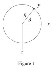
Refer to Figure 1.
Calculate the moment along
Substitute
Calculate the moment along
Substitute
Sketch the cross section of the rectangular post as shown in Figure 2.
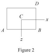
Refer to Figure 2.
Calculate the area
Substitute
Calculate the moment of inertia along
Substitute
Calculate the moment of inertia along
Substitute
The location of point D along
The location of point D along
Calculate the stress
Substitute
The stress
Calculate the stress at point D
Substitute
Calculate the value of
Differentiate both sides of the Equation with respect to
Substitute
Substitute
Therefore, the value of
(b)
Find the values of stress at A, B, C, and D.
(b)
Answer to Problem 149P
The stress at A is
The stress at B is
The stress at C is
The stress at D is
Explanation of Solution
Given information:
The radius of the circular plate is
The width of the rectangular post is
The applied force is
Calculation:
Refer to part (a).
The value of
The bending moment along x direction is
Substitute
The bending moment along z direction is
Substitute
Calculate the stress at A
Refer to Figure 2 in part (a).
The location of point A along
The location of point A along
Substitute
Hence, the stress at A is
Calculate the stress at B
Refer to Figure 2 in part (a).
The location of point B along
The location of point B along
Substitute
Hence, the stress at B is
Calculate the stress at C
Refer to Figure 2 in part (a).
The location of point C along
The location of point C along
Substitute
Hence, the stress at C is
Calculate the stress at D
Refer to Figure 2 in part (a).
The location of point D along
The location of point D along
Substitute
Therefore, the stress at D is
Want to see more full solutions like this?
Chapter 4 Solutions
Loose Leaf For Mechanics Of Materials Format: Looseleaf


- Knowing that, for the plate shown, the allowable stress is 125 MPa, determine the maximum allowable value of P when (a) r=12 mm, (b) r= 18 mmarrow_forwardKnowing that the clamp shown has been tightened until P= 400 N, determine (a) the stress at point A, (b) the stress at point B, (c) the location of the neutral axis of section a-a.arrow_forwardA fabric used in air-inflated structures is subjected to a biaxial loading that results in normal stresses ox = 18 ksi and oz = 24 ksi.Knowing that the properties of the fabric can be approximated as E = 12.6 x 10 psi and v = 0.34, determine the change in length of (a) side AB, (b) side BC, (c) diagonal AC.arrow_forward
- Two steel plates are to be held together by means of 16-mm-diameter high-strength steel bolts fitting snugly inside cylindrical brass spacers.Knowing that the average normal stress must not exceed 200 MPa in the bolts and 130 MPa in the spacers, determine the outer diameter of the spacers that yields the most economical and safe design.arrow_forwardStraight rods of 0.30-in. diameter and 200-ft length are sometimes used to clear underground conduits of obstructions or to thread wires through a new conduit. The rods are made of high-strength steel and, for storage and transportation, are wrapped on spools of 5-ft diameter. Assuming that the yield strength is not exceeded, determine (a) the maximum stress in a rod, when the rod, which was initially straight, is wrapped on the spool, (b) the corresponding bending moment in the rod. Use E= 29 * 106 psi.arrow_forwardA rod must not stretch more than 6 mm when the tension in the wire is 8 kN. Knowing that E = 105 GPa and that the maximum allowable normal stress is 150 MPa, determine the smallest diameter (mm) rod that should be used.arrow_forward
- The aluminum rod AD is fitted with a jacketthat is used to apply a hydrostatic pressure of5000 psi to the 12-in. portion BC of the rod.Knowing that E = 10.1 × 10⁶ psi and v = 0.36,determine the forces that should be appliedto the ends A and D of the rod if the axialstrain in portion BC of the rod is to remainzero as the hydrostatic pressure is applied.Determine the forces that should be appliedto the ends A and D if the total length AD ofthe rod is to remain unchanged.arrow_forwardKnowing that the couple shown acts in a vertical plane, determine the stress at (a) point A, (b) point B.arrow_forwardA rod must not stretch more than 6 mm when the tension in the wire is 8 kN. Knowing that E = 105 GPa and that the maximum allowable normal stress is 150 MPa, determine the corresponding maximum length of the rod (m).arrow_forward
- Two gage marks are placed exactly 250 mm apart on a 12-mm-diameter aluminum rod with E = 73 GPa and an ultimate strength of 140 MPa. Knowing that the distance between the gage marks is 250.28 mm after a load is applied, determine the stress in the rodarrow_forwardTwo solid cylindrical rods AB and BC are welded together at B and loaded as shown. Knowing that d1 = 30 mm and d2=50 mm,find the average normal stress at the midsection of (a) rod AB,(b) rod BC.arrow_forwardTwo solid cylindrical rods AB and BC are welded together at B and loaded as shown. Knowing that d1 = 50 mm and d2 = 30 mm, find the average normal stress at the midsection of (a) rod AB, (b) rod BC.arrow_forward
 Elements Of ElectromagneticsMechanical EngineeringISBN:9780190698614Author:Sadiku, Matthew N. O.Publisher:Oxford University Press
 Mechanics of Materials (10th Edition)Mechanical EngineeringISBN:9780134319650Author:Russell C. HibbelerPublisher:PEARSON
 Thermodynamics: An Engineering ApproachMechanical EngineeringISBN:9781259822674Author:Yunus A. Cengel Dr., Michael A. BolesPublisher:McGraw-Hill Education
 Control Systems EngineeringMechanical EngineeringISBN:9781118170519Author:Norman S. NisePublisher:WILEY
 Mechanics of Materials (MindTap Course List)Mechanical EngineeringISBN:9781337093347Author:Barry J. Goodno, James M. GerePublisher:Cengage Learning
 Engineering Mechanics: StaticsMechanical EngineeringISBN:9781118807330Author:James L. Meriam, L. G. Kraige, J. N. BoltonPublisher:WILEY