
Concept explainers
Videos
(a) Determine the ratio vo/is in the op amp circuit of Fig. 5.54.
(b) Evaluate the ratio for R1 = 20 kΩ, R2 = 25 kΩ, R3 = 40 kΩ.
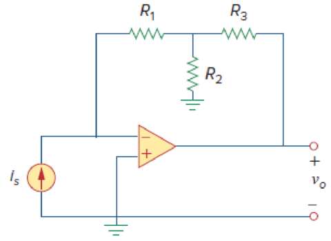
Figure 5.54
For Prob. 5.15.
(a)
Calculate the ratio
Answer to Problem 15P
The ratio
Explanation of Solution
Given data:
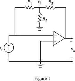
Refer Figure 5.54 in the textbook for the op amp circuit.
Calculation:
Modify the Figure 5.54 by indicating the node voltage
Apply Kirchhoff's current law to the node
Consider the expression for the current
Substitute equation (2) in (1).
Simplify the equation as follows.
Conclusion:
Thus, the ratio
(b)
Find the value for the ratio
Answer to Problem 15P
The value for
Explanation of Solution
Given data:
Consider that the resistors
Calculation:
Substitute
Conclusion:
Thus, the value for
Want to see more full solutions like this?
Chapter 5 Solutions
FUND.OF ELECTRIC CIRCUITS (LL)-W/ACCESS


- The op amp in the circuit shown is ideal. Calculate vo if va=2 V and vb=0 V.arrow_forward1. Find vo in the circuit shown if va=0.1 V and vb=0.25 V. 2. If vb=0.25 V, how large can va be before the op amp saturates? 3. If va=0.10 V, how large can vb be before the op amp saturates? 4. Repeat (a), (b), and (c) with the polarity of vb reversed?arrow_forwardCan you please show me what equation you use and calculate: Find the voltage vo assuming the op amp is ideal and the voltages are va = 3, vb = 9, vc = 5, and vd = 6arrow_forward
- 1. For the circuit shown, show that if ΔR<<R, the output voltage of the op amp is approximately vo≈Rf(R+Rf)R2(R+2Rf)(−ΔR)vin. 2. Find vo if Rf=470 kΩ, R=10 kΩ, ΔR=95 Ω, and vin=15 V. 3. Find the actual value of vo in (b).arrow_forwardBased on the op amp circuit in Figure, answer the following questions,assuming an ideal op-amp. Given:V1 = 1 VI2 = 2 mAV3 = 0.5 VRa = 2 kΩRb = 1 kΩRc = 5 kΩRd = 10 kΩVx = 4VIb = 3.5mANow I need to determine Vo and the current and power through Rd.Please help, Thank youarrow_forward5.40 Referring to the circuit shown in Fig. 5.77, determine Vo in terms of V1 and V2.arrow_forward
- The op amp shown below has a maximum output voltage range from −5 to +5 V. The maximum output current magnitude of the op amp is 20 mA. The slew-rate limit is 5 V/μs. a. Find the full-power bandwidth of the op amparrow_forwardHow to create a circuit that has three varying input voltages and one output voltage that is equal to the average of the three? Vin = V1, V2, V3Vout = (V1 + V2 + V3) / 3 Example:V1 = 750mV, V2 = 700mV, V3 = 800mVVo = 750mV You can only use resistors and OpAmps (operational amplifiers), show circuit schematic and computations/formulas usedarrow_forwardIn the figure above, R_{a}Ra=1kΩ, R_{b}Rb=2kΩ, R_{c}Rc=3kΩ. R_{f}Rf=12kΩ. The sources are v_{a}va=−4V, v_{b}vb=+2V, and v_{c}vc=1V. The power supplies for the op-amp are +15V and −15V. What is the value of v_{o}vo? Notice that this op amp circuit might saturate, and you need to consider that possibility in your answer. Give your answer in volts and omit the units from your answer. What must be R_aRa be changed to so that v_{o}vo is 13 V? Give your answer in kilo-ohms with no units.arrow_forward
- Assume that the op amp in the circuit shown is ideal. 1. Calculate vo for the following values of vs: 0.4, 2.0, 3.5, −0.6, −1.6, and −2.4 V. 2. Specify the range of vs required to avoid amplifier saturation.arrow_forwardIn the op-amp circuit shown below, find V0. 30 kQ Select one: O avo=6V O b.vo=3v c. None of the above ) d.VO=9Varrow_forwardAn op-amp with an open-loop gain of 3x10⁶ and Vcc = 12 V has an inverting-input voltage of 6.7 microVolts and a non-inverting input voltage of 5.4 microVolts. What is its output voltage? Be sure to round your answer to the nearest single digital decimal place. Do not enter units. As an example, if you calculate 7.39 Volts then enter 7.4 as your submitted answerarrow_forward
 Introductory Circuit Analysis (13th Edition)Electrical EngineeringISBN:9780133923605Author:Robert L. BoylestadPublisher:PEARSON
 Delmar's Standard Textbook Of ElectricityElectrical EngineeringISBN:9781337900348Author:Stephen L. HermanPublisher:Cengage Learning
 Programmable Logic ControllersElectrical EngineeringISBN:9780073373843Author:Frank D. PetruzellaPublisher:McGraw-Hill Education
 Fundamentals of Electric CircuitsElectrical EngineeringISBN:9780078028229Author:Charles K Alexander, Matthew SadikuPublisher:McGraw-Hill Education
 Electric Circuits. (11th Edition)Electrical EngineeringISBN:9780134746968Author:James W. Nilsson, Susan RiedelPublisher:PEARSON
 Engineering ElectromagneticsElectrical EngineeringISBN:9780078028151Author:Hayt, William H. (william Hart), Jr, BUCK, John A.Publisher:Mcgraw-hill Education,