
Concept explainers
Videos
In the circuit shown in Fig. 5.62, find k in the voltage transfer function vo = kvs.
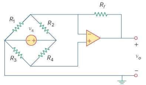
Figure 5.62
For Prob. 5.24.
Derive the expression for k in the voltage transfer function
Answer to Problem 24P
The expression for k is
Explanation of Solution
Given data:
Refer to Figure 5.62 in the textbook for the given op amp circuit.
Calculation:
Modify the Figure 5.62 by indicating the node voltages
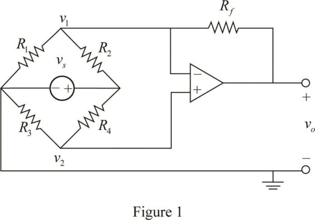
From the properties of ideal op amp, consider that the voltage across the two input terminals of op amp is equal to zero.
Apply Kirchhoff's current law to the node
Apply Kirchhoff's current law to the node
Simplify the equation as follows.
Substitute equation (1) in (3).
Substitute equation (4) in (2).
Consider the expression for the voltage transfer function.
Compare equations (5) and (6).
Conclusion:
Thus, the expression for k is
Want to see more full solutions like this?
Chapter 5 Solutions
FUND.OF ELECTRIC CIRCUITS (LL)-W/ACCESS


- Can you please help explain and answer the question below using the concept of operational amplifiers: The op amp in the circuit below is ideal. Calculate the following ia, Va, Vo, and io.arrow_forwardPlease explain this circuit because I still don't understand, this circuit is used for an experiment to calculate SR (Slew Rate) on the op amparrow_forwardIn the circuit shown in Figure below, given İ =10 ∠0°A, calculate the values of İ1, İ2, and İ3arrow_forward
- The op amp in the circuit shown shown is ideal. Calculate vo when vg equals 3 V.arrow_forwardCan you please show me what equation you use and calculate: Find the voltage vo assuming the op amp is ideal and the voltages are va = 3, vb = 9, vc = 5, and vd = 6arrow_forwardQ)Design an electronic circuit that can satisfy the following equation (dvi) Vo=—R o c dt using an operational amplifier.arrow_forward
- 6. Which of the following characteristics does not necessarily apply to an op amp?to. high gainb. High input impedancec. High powerd. Low output impedancearrow_forwardElectrical Engineering a) design a class A amplifier that can deliver 5w to an 8 load vcc=15v. using a transistor tip 31 b) design a class B amplifier that can deliver 40w . procide your self a load vcc=15v using a transistor tip 31.arrow_forwardInstrumentation Amplifier Design an Instrumentation Amplifier with a Voltage Output of 5v. Assuming that you have a 1k ohms on all resistors excluding the Rgain, with V1 = 10v and V2 = 15v with a frequency of 60hz. Use the proper amplifier on this, which is designed to work as a Precision Operational Amplifier. Take a screenshot of your schematic and the graph of Voltage Input and Voltage Output.arrow_forward
 Introductory Circuit Analysis (13th Edition)Electrical EngineeringISBN:9780133923605Author:Robert L. BoylestadPublisher:PEARSON
 Delmar's Standard Textbook Of ElectricityElectrical EngineeringISBN:9781337900348Author:Stephen L. HermanPublisher:Cengage Learning
 Programmable Logic ControllersElectrical EngineeringISBN:9780073373843Author:Frank D. PetruzellaPublisher:McGraw-Hill Education
 Fundamentals of Electric CircuitsElectrical EngineeringISBN:9780078028229Author:Charles K Alexander, Matthew SadikuPublisher:McGraw-Hill Education
 Electric Circuits. (11th Edition)Electrical EngineeringISBN:9780134746968Author:James W. Nilsson, Susan RiedelPublisher:PEARSON
 Engineering ElectromagneticsElectrical EngineeringISBN:9780078028151Author:Hayt, William H. (william Hart), Jr, BUCK, John A.Publisher:Mcgraw-hill Education,