
ELECTRICAL WIRING:RESIDENTAL-6 PLANS
18th Edition
ISBN: 9781305098329
Author: MULLIN
Publisher: CENGAGE L
expand_more
expand_more
format_list_bulleted
Concept explainers
Videos
Textbook Question
Chapter 5, Problem 15R
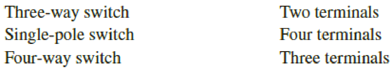
Match the following switch types with the correct number of terminals for each.
Expert Solution & Answer

Trending nowThis is a popular solution!

Students have asked these similar questions
Explain mounting arrangement and positioning of switch boards
1What is the condition of a one-way switch if it has no resistance between terminals at both
toggle positions 1 & 2? Is it still usable or not? Explain.
2 A one-way switch is in ON position if its resistance between terminals is almost zero.
Explain.
3. Can a push button switch be used to control a lamp? Explain.
4. Identify the ON and OFF positions of the MCB.
5. A bulb or lamp is busted or broken if its resistance is less than 100Q. True or False?
6.
when seeking to measure the voltage of an industrial power supply (600 Volts AC) an
electrician needs to do the following to prepare the Simpson 260 meter for
measurement (insert the words to make the following statements correct).
a. Set the function switch to
b. The black lead should be inserted in the
jack.
C. The red lead should be inserted in the
jack.
d. The range switch should be set to the
position.
Did you note the safety warnings in this section? Fairly significant, eh?!
Nothing to mess around with!!
7.
Why must you "zero" the meter (adjust it for zero (0)) when measuring resistance?
8.
Describe the steps needed to accomplish the task of zeroing the meter. (4pts)
For the following questions, refer to section 4.19 in the Simpson meter manual.
9.
The Rx 1 resistance range is intended for resistances between
and
Ω.
10. The R x 100 range is intended for resistances between
and
Ω.
11. The Rx 10,000 range is intended for resistances over
0450…
Chapter 5 Solutions
ELECTRICAL WIRING:RESIDENTAL-6 PLANS
Ch. 5 - The identified grounded circuit conductor must be...Ch. 5 - Explain how lighting switches are rated.Ch. 5 - Prob. 4RCh. 5 - Prob. 5RCh. 5 - To control a lighting load from one control point,...Ch. 5 - Prob. 7RCh. 5 - Complete the connections in the following...Ch. 5 - Complete the connections for the diagram....Ch. 5 - A three-way switch may be compared to a _____...Ch. 5 - Prob. 11R
Ch. 5 - Complete the connections in the following...Ch. 5 - When connecting 4-way switches, care must be taken...Ch. 5 - Show the connections for a ceiling outlet that is...Ch. 5 - Match the following switch types with the correct...Ch. 5 - When connecting single-pole, 3-way, and 4-way...Ch. 5 - What section of the Code emphasizes the fact that...Ch. 5 - If you had to install an underground 3-wire feeder...Ch. 5 - Is it always necessary to attach the bare...Ch. 5 - List the methods by which an equipment grounding...Ch. 5 - When two nonmetallic-sheathed cables (Type NM-B)...Ch. 5 - Define an equipment grounding conductor.Ch. 5 - When metal toggle switchplates are used with...Ch. 5 - Does the Code permit the ampacity of switch legs...Ch. 5 - Prob. 26RCh. 5 - Prob. 27R
Additional Engineering Textbook Solutions
Find more solutions based on key concepts
With respect to the circuit in Fig. 5.90, (a) employ Thévenin’s theorem to determine the equivalent network see...
Loose Leaf for Engineering Circuit Analysis Format: Loose-leaf
Identify the type of input and output configuration for each diff-amp in Figure 18-35.
Electronics Fundamentals: Circuits, Devices & Applications
The current source in the circuit shown generates the current pulse
Find (a) v (0); (b) the instant of time gr...
Electric Circuits. (11th Edition)
Explain the main function of each of the following major components of a PLC: a. Processor module (CPU) b. I/O ...
Programmable Logic Controllers
Write the nodal equations for the network of Fig. 8.137 using the general approach. Find the nodal voltages usi...
Introductory Circuit Analysis (13th Edition)
What is the color code for a 365- five-band precision resistor with a tolerance of 5 percent?
ELECTRICITY FOR TRADES (LOOSELEAF)
Knowledge Booster


Learn more about
Need a deep-dive on the concept behind this application? Look no further. Learn more about this topic, electrical-engineering and related others by exploring similar questions and additional content below.Similar questions
- Complete the wiring below, such that the two sensors are connected in series and capable of controlling the given load. SENSORS in SERIES ... Brown Brown 0-30 Vpc SUPPLY Black Black PNP PNP Blue Bluearrow_forwardExplain a DPDT switch with a drawing and how they work. Also explain NC and NO on the drawing. Please answer in typing format please ASAP for the like Please it's urgentarrow_forwardWhat is the size of the opening of a switch (device) box for a single device? _________________________________arrow_forward
- Compare the nested and the NPC topologies in terms of the blocking voltage for the switches employed in one leg. Assume that both topologies have four levels and are generating the same output voltage. Disregard any saftey margin while specifying the voltages for each power switch.arrow_forward21/ Which Insulators can be used for both horizontal and vertical positioning? A. PIN TYPE INSULATORS B. SHACKLE TYPE INSULATORS C. SUSPENSION TYPE INSULATORS D. POST TYPE INSULATORSarrow_forwardPlease help with the following questions, thank you. Calculate the following : 1) At what voltage is the switching point? 2) The hysteresis spread ?arrow_forward
- 12. Which Insulators can be used for both horizontal and vertical positioning? A. SUSPENSION TYPE INSULATORS B. SHACKLE TYPE INSULATORS C. PIN TYPE INSULATORS D. POST TYPE INSULATORSarrow_forwardI have an O Gauge track and would like to convert it into a “sensored” track. Additionally, I would like to connect that track to an ESP-WROOM-32 board that should flash an LED whenever the track detects a non-moving train. Please list all the components (and how many of each) needed. Also, what’s the procedure for connecting the components?arrow_forwardBasic Electrical Engineering (UPVOTE WILL BE GIVEN. WRITE THE COMPLETE SOLUTIONS. NO LONG EXPLANATION NEEDED. ANSWER IN 2 DECIMAL PLACES. BOX THE FINAL ANSWERS.) Determine the following: a. RT = ? b. IT = ? c. PT = ?arrow_forward
arrow_back_ios
SEE MORE QUESTIONS
arrow_forward_ios
Recommended textbooks for you
 EBK ELECTRICAL WIRING RESIDENTIALElectrical EngineeringISBN:9781337516549Author:SimmonsPublisher:CENGAGE LEARNING - CONSIGNMENT
 Delmar's Standard Textbook Of ElectricityElectrical EngineeringISBN:9781337900348Author:Stephen L. HermanPublisher:Cengage Learning
EBK ELECTRICAL WIRING RESIDENTIAL
Electrical Engineering
ISBN:9781337516549
Author:Simmons
Publisher:CENGAGE LEARNING - CONSIGNMENT
Delmar's Standard Textbook Of Electricity
Electrical Engineering
ISBN:9781337900348
Author:Stephen L. Herman
Publisher:Cengage Learning
Star Delta Starter Explained - Working Principle; Author: The Engineering Mindset;https://www.youtube.com/watch?v=h89TTwlNnpY;License: Standard Youtube License