
Industrial Motor Control
7th Edition
ISBN: 9781133691808
Author: Stephen Herman
Publisher: Cengage Learning
expand_more
expand_more
format_list_bulleted
Videos
Textbook Question
Chapter 5, Problem 15RQ
Refer to the circuit shown in Figure 5-29. In this circuit, the HR contactor is equipped with five contacts. Three are load contacts and two are auxiliary contacts. From looking at the schematic diagram, how is it possible to identify which contacts are the load contacts and which are the auxiliary contacts?
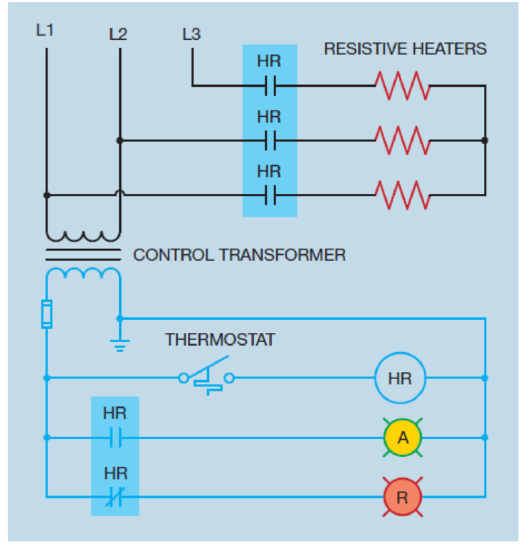
Figure 5-29 The contactor contains both load and auxiliary contacts.
Expert Solution & Answer

Trending nowThis is a popular solution!

Chapter 5 Solutions
Industrial Motor Control
Ch. 5 - Prob. 1RQCh. 5 - Prob. 2RQCh. 5 - Explain the difference between auxiliary contacts...Ch. 5 - Prob. 4RQCh. 5 - What is optoisolation and what is its main...Ch. 5 - What pin numbers are connected to the coil of an...Ch. 5 - An 11-pin control relay contains three sets of...Ch. 5 - What is the purpose of the shading coil?Ch. 5 - Refer to the circuit shown in Figure 5-29. Is the...Ch. 5 - What is the difference between a motor starter and...
Knowledge Booster


Learn more about
Need a deep-dive on the concept behind this application? Look no further. Learn more about this topic, mechanical-engineering and related others by exploring similar questions and additional content below.Similar questions
- Refer to the circuit shown in Figure 7-10. If wire number 11 were disconnected at the normally open auxiliary M contact, how would the circuit operate? Figure 7-10 Numbers are placed beside all components.arrow_forwardRefer to the circuit shown in Figure 4221. Assume that the THIRD SPEED push button is pressed. The motor starts in second speed, skipping first speed. After 5 seconds, the motor accelerates to third speed. Which of the following could cause this problem? a. S1 contactor coil is open. b. CR1 contactor coil is open. c. TRl timer coil is open. d. S1 load contacts are shorted.arrow_forwardRefer to the circuit shown in Figure 25–5. Assume that timer TR1 is set for a delay of 10 seconds and timer TR2 is set for a delay of 5 seconds. When the START button is pressed, the motor starts. After 10 seconds the S1 contacts open and the motor continues to accelerate, but never reaches full speed. After a delay of about 30 seconds, the motor trips out on overload. Which of the following could cause this problem? TR1 coil is open. S2 coil is open. S1 coil is open. R coil is open.arrow_forward
- Refer to the circuit shown in Figure 108. In this circuit, the jog button has been connected incorrectly. The normally closed section has been connected in parallel with the run push button and the normally open section has been connected in series with the holding contacts. Explain how this circuit operates.arrow_forwardRefer to the circuit shown in Figure 42–21. Assume that a fused jumper is connected across terminals 1 and 3 of TR2 timer. What would happen if the jumper were left in place and the FIRST SPEED push button pressed? The motor would start in its lowest speed and progress to second speed, but never increase to third speed. The motor would start operating immediately in third speed. The motor would not start. The motor would start in second speed and then increase to third speed.arrow_forwardRefer to the circuit shown in Figure 109. In this circuit the jog push button has again been connected incorrectly. The normally closed section of the button has been connected in series with the normally open run push button and the normally open section of the jog button is connecting in parallel with the holding contacts. Explain how this circuit operates.arrow_forward
- Refer to the circuit shown in Figure 107. Assume that when the start button is pressed the motor does not start, but when the inch push button is pressed the motor runs at reduced speed. Which of the following could NOT cause this problem? a. The control transformer fuse is blown. b. M starter coil is defective. c. The start push button is defective. d. The stop push button is defective.arrow_forwardRefer to the circuit shown in Figure 5-29. Is the thermostat contact normally open, normally closed, normally closed held open, or normally open held closed? Figure 5-29 The contactor contains both load and auxiliary contacts.arrow_forwardRefer to the circuit shown in Figure 97. Assume that when the forward push button is pressed the motor does not start, but when the reverse push button is pressed the motor will start in the reverse direction. When the stop button is pressed the motor stops running. Which of the following could NOT cause this problem? a. The forward push button is defective. b. The F starter coil is open. c. The overload auxiliary contact is open. d. The normally closed R contact is open.arrow_forward
- Following the procedure discussed in Chapter 7, place wire numbers on the schematic in Figure 8–7. Place corresponding wire numbers on the components shown in Figure 8–8.arrow_forwardRefer to the circuit shown in Figure 241. Assume that timer TR is set for a delay of 10 seconds. When the START button is pressed, the motor starts in low speed. After a delay of 30 seconds the motor is still in its lowest speed and has not accelerated to normal speed. Which of the following could not cause this condition? a. The START button is shorted. b. Timer coil TR is open. c. Contactor coil R is open. d. Timed contact TR did not close after a delay of 10 seconds.arrow_forwardRefer to the circuit shown in Figure 33–7. When the low speed push button is pressed, the motor begins to run in low speed. When the high speed push button is pressed, the motor stops running. Which of the following could cause this problem? The 1L contactor coil is open. H contactor coil is open. PR relay coil is open. The 2L contactor coil is open.arrow_forward
arrow_back_ios
SEE MORE QUESTIONS
arrow_forward_ios
Recommended textbooks for you
 Understanding Motor ControlsMechanical EngineeringISBN:9781337798686Author:Stephen L. HermanPublisher:Delmar Cengage Learning
 Electrical Transformers and Rotating MachinesMechanical EngineeringISBN:9781305494817Author:Stephen L. HermanPublisher:Cengage Learning
Understanding Motor Controls
Mechanical Engineering
ISBN:9781337798686
Author:Stephen L. Herman
Publisher:Delmar Cengage Learning
Electrical Transformers and Rotating Machines
Mechanical Engineering
ISBN:9781305494817
Author:Stephen L. Herman
Publisher:Cengage Learning
Mod-01 Lec-16 Basics of Instrumentation; Author: nptelhrd;https://www.youtube.com/watch?v=qbKnW42ZM5c;License: Standard YouTube License, CC-BY